 View figure. View figure. |
This chapter describes how to set up a database to be managed by a Control Center service machine.
Prior to performing the database setup process detailed in this chapter you should have:
Prior to setting up a database to be managed by a Control Center service machine, you will need to make some decisions about the operation of the database. Control Center allows you to manage the operational functions of databases in different ways, adapting to the needs of each specific database. Decisions such as logmode; what type of archiving will be used (database or User); whether archives will use predefined tapes, scratch tapes, or disk files; and how often archives will be taken, need to be made prior to establishing a database under Control Center.
Another important consideration for a database is the naming convention chosen for the database machine name and the database dbname. For ease of use and to eliminate confusion, the database machine name should be identical to the dbname. The System Administration tools rely on an IUCV communication between the Control Center service machine and the database machine. Most references within this manual and the Control Center interface for these tools will therefore use the term database to refer to the database machine name. Only Database Administration tools, which interface with the database as database applications, utilize the database dbname instead of the database machine name.
Control Center provides the capability to assign a database machine nickname in file SQLMSTR DIRECTRY. Therefore, if a database machine name differs from the dbname, it can be assigned a nickname equal to the dbname. This will allow users to enter either the database machine name or nickname (dbname) when using the Control Center panel interface. Control Center will automatically convert the nickname to the machine name prior to executing the requested tool.
Notes:
Preliminary Setup
Control Files Setup
Database Machine Setup
Setup Verification
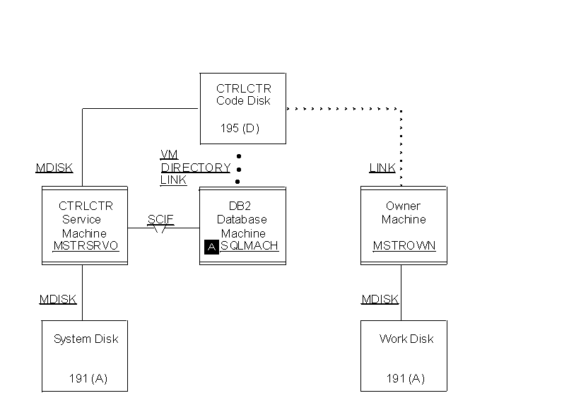
Steps 1 through 5 prepare your database machine for interfacing with the Control Center product. Figure 6 summarizes what you will accomplish.
Figure 6. Database Machine in a Control Center Environment. Database machine SQLMACH (A) has been added to the environment shown in Figure 7 using the database setup process. Service machine MSTRSRVO manages SQLMACH and is the owner of the Control Center code disk. A shared service machine (MSTRSRVS) could have been used instead of MSTRSRVO; it would link to the same code disk as SQLMACH. Communications between SQLMACH and MSTRSRVO is through the SCIF interface.
View figure.
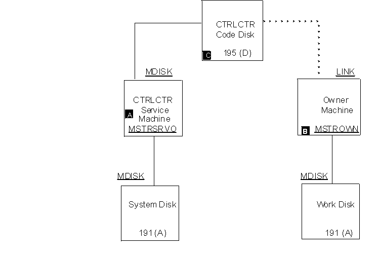
Figure 7. Virtual Machines and Minidisks in a Control Center Service Machine Full Installation. MSTRSRVO (A) is the owner of the Control Center code disk (C). MSTROWN (B) links to the code disk in READ mode and is defined as the logical owner of MSTRSRVO.
 View figure.
To begin the database machine setup, log on to the MAINT virtual machine.
Change the VM directory entries for the database machine to activate the Secondary Console Interface Facility (SCIF) and to link the Control Center code disk. Refer to the appropriate Virtual Machine Operation manuals for a complete description of these statements.
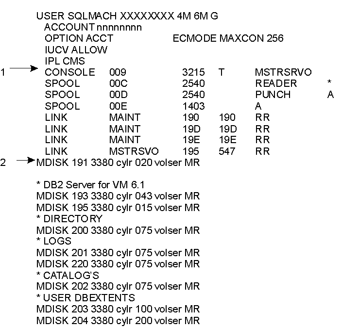
Figure 8. Example VM Directory Control Statements for a Database Machine
 View figure. View figure. |
| Note: | The managing service machine can either be the owner of the code disk or a service machine that shares a code disk. |
Instead of including the above statement in the VM directory, you may, during a later step, add a LINK statement to the PROFILE EXEC of the SQLMACH machine.
| Note: | SQLMACH must be authorized to access the Control Center code disk in READ mode. |
| Important: |
|---|
|
|
After you have made the VM directory statement changes for the database machine, update the VM directory using your local operating procedures.
Under normal operations the SQLMACH machine should be autologged each time the CPU is IPLed. The SQLMACH machine should therefore be included in the list of virtual machines that are autologged each time the CPU is IPLed.
For proper startup of each database when the CPU is IPLed, the database machine must be autologged after the managing Control Center service machine.
| Important: |
|---|
|
|
Preliminary setup is now complete. Log off the MAINT machine.
Steps 6 through 15 generate the database control files listed below. These files are kept on the managing service machine's 191 A-disk.
Additionally, Control Center control files SQLMSTR DIRECTRY and DBINIT CONTROL are updated with entries for the new database. These files are kept on the service machine's 195 code disk.
| Important: |
|---|
|
If the managing service machine is using a shared code disk, additional steps are required to migrate the updated Control Center control files to the code disk. |
The Control Center service machine must be operational to complete steps 8 through 12 and for the verification process. Refer to DB2 Server for VM Control Center Program Directory.
Log on to the MSTROWN machine or any machine that has Control Center Administrator authority on the service machine specified on the CONSOLE statement in Setup Step 2 (the managing Control Center service machine).
Link and access the Control Center code disk in READ mode with an available virtual device address (CUU) and access mode |(for example, 195 D).
Notes:
To establish communications with MSTRSRV and to start Control Center in panel mode, enter these commands at the CMS command prompt:
SQM (MSTRSRV
SQM
Replace MSTRSRV with the machine ID of your service machine.
The Control Center Main Menu should now be displayed. Select Option N (New Database Setup) to display the panel shown in Figure 9. Enter the database machine name in field (A).
Figure 9. New Database Setup Panel
+--------------------------------------------------------------------------------+
| mm/dd/yyyy                      CONTROL CENTER                      hh:mm:ss   |
|*---------------------------- New Database Setup ----------------------------*  |
|| Command ==>                                              CTRLID: MSTRSRV   |  |
||    Database   => (A)                                      NODE:  VMSYSTM   |  |
||                                                                            |  |
||  This function allows the creation of Control Center files required to     |  |
||  manage a new database (PARMS, TAPES, ARISPOOL).  The PARMS file           |  |
||  will contain parameters associated with database operations               |  |
||  including startup, utility/tape and archiving parameters.  The            |  |
||  TAPES file will contain information about tapes or disks required         |  |
||  to archive and recover the database.  The ARISPOOL file defines           |  |
||  VM Dataspace usage.                                                       |  |
||                                                                            |  |
||  In addition to this setup process, the DBPROF EXEC located on the         |  |
||  CTRLCTR 191 (A) disk must be copied to the database 191 (A) disk and      |  |
||  renamed to PROFILE EXEC.  Without this PROFILE EXEC, the data base        |  |
||  will not communicate properly with CTRLCTR.  The database VM              |  |
||  directory must also direct secondary console output to the CTRLCTR        |  |
||  machine as defined in the database setup documentation.                   |  |
||                                                                            |  |
||  Select PF4 to create PARMS file, PF5 for TAPES file, PF6 for VMDSS file.  |  |
||                                                                            |  |
|*---------------------------------------------------------------SQMDBSET-----*  |
|PF: 1 Help   3 End   4 PARMS file    5 TAPES file    6 ARISPOOL file            |
+--------------------------------------------------------------------------------+
Press PF4 (PARMS file) to create the database parameters file. Refer to About the Database Parameters Tool for a complete description of the Database Parameters tool.
Control Center maintains a set of database startup and control parameters for each database machine it manages. Parameters for each database managed by the service machine are saved in separate files named database PARMS, where database is the database machine ID, and are kept on the Control Center service machine's 191 A-disk. Database parameters are separated into the | following general groups:
Complete information about the database parameters file, including the Data Restore enablement, can be found in Database Parameters File.
Terminology Used in this Section:
Press PF5 (TAPES file) to create the database TAPES file. Refer to Chapter 11, Tape Management Tool for a complete description of the Tape Management tool.
A separate database TAPES file is maintained by Control Center for each database machine it manages. Tapes files are named database TAPES, where database is the database machine ID, and are kept on the Control Center service machine's 191 A-disk.
Control Center uses the database TAPES file to maintain a list of output media assigned for usage during database archive, log archive, and trace activities. It must be defined prior to starting the database under Control Center control. When the database is started, FILEDEF and LABELDEF commands will be issued for the output media identified in this file. Control Center references and updates this file as necessary during archive, log archive, and trace activities.
It is the responsibility of the database administrator to assure that the TAPES file is created correctly, with valid tape volids and with series numbers that match those identified in the database parameters file. The SERIES parameters in the parameters file indicate which group of tapes within the TAPES file will be used for the next archive. After initially setting these parameters, Control Center will maintain the values automatically when archives are performed.
A full database archive will use as many archive tapes as it needs that have the same series number. Each subsequent log archive after a full archive will use tapes within the same series as the previous full archive. Even though tapes may be available elsewhere within the TAPES file, Control Center will not use them unless they have the same series number as that specified within the database parameters file.
| Important: |
|---|
|
Output media with the same series number are considered by Control Center to belong together as a single logical group. |
An important consideration when creating this file is determining how many series of tapes should be included. At least three series should be created, although Control Center will operate with fewer. It should be remembered that if an archive fails, you would want to have at least one previous successful archive to fall back on.
Each tape included in the TAPES file should be labelled and assigned to the database machine which will be using it. This must be done by using whatever tape management system is installed on your system.
If the DYNAM/T or VMTAPE product is used at your site, the SCRATCH TAPE ACQUISITION (S) option of the Tape Management tool can be used to add tapes to this file. This function will request that a scratch tape be mounted, and will acquire ownership of the tape for the indicated retention period and place it in the database TAPES file.
| Usage Consideration: | If you have DYNAM/T installed and use DYNOPEN as your tape method, the SCRATCH TAPE ACQUISITION tool cannot be used. Only DYNMOUNT supports the use of scratch tape acquisition. Check the SQLMSTR Control file to determine if DYNOPEN has been selected as the tape method for DYNAM/T, if this is the case, scratch tape acquisition will fail. |
| Important: |
|---|
|
Check your tape facility to ensure that the RETENTION period parameter is implemented correctly. |
If you are running under logmode Y or A, therefore doing only full database archives, you will only need to include ARCHIVE tapes within the TAPES file. You must assure that enough tapes are listed for each series to perform a complete database archive. You should also have at least one extra tape available in each series to allow for database growth. When a database starts up, every ARCHIVE tape in the specified series will be LABELDEFed for a multivolume archive. If enough tapes are not available to complete the archive, the results will be unpredictable (dependent upon the tape management system being used).
If you are running under logmode L, performing log archiving, then you will need to include LOG tapes within the TAPES file. These tapes will be used to dump the database log file when it becomes full.
| Important: |
|---|
|
Control Center expects that the entire log file will fit on a single LOG tape. This will enable log archives to be taken while the database remains up. If the log file is larger than what will fit on a single tape, then Control Center will not operate properly. This implementation is due to a restriction in CMS and database which prevents the LABELDEF command from being reissued while the database is running. |
If you are doing tracing within the database, then you will need to include TRACE tapes within the TAPES file.
|For a complete description of the TAPES file format, refer to Database TAPES File Format.
The following is an example database TAPES file for archiving to tape. It specifies that Control Center will rotate three sets of archive tapes (series 100, 200, 300). It also indicates that logmode L (log archiving) will be used. Each series has three ARCHIVE tapes, allowing for a database size that will fit entirely on three tapes. Each series also has two LOG tapes. This essentially allows for only one log archive between full database archives, since the first step of a full database archive under logmode L will be to perform a Log Archive.
You must have one LOG tape more than you expect to need between full database archives. Control Center will request a scratch tape to be mounted when no tapes are available for a given series in the database TAPES file. This cannot perform properly if VMTAPE or DYNAM/T is not being used. In an effort to prevent running out of tapes, Control Center will warn the DBA(s) whenever the last tape in a series is mounted.
Figure 10. Example TAPES File for Archiving to Tape
                                           VOLID/
 SERIES  TYPE     DATE   TIME     STATUS   FILENAME  FILETYPE  FM   CUU   CI
  100    ARCHIVE  00000  00:00:00 UNUSED   VOL100
  100    ARCHIVE  00000  00:00:00 UNUSED   VOL101
  100    ARCHIVE  00000  00:00:00 UNUSED   VOL102
  100    LOG      00000  00:00:00 UNUSED   VOL110
  100    LOG      00000  00:00:00 UNUSED   VOL111
  200    ARCHIVE  00000  00:00:00 UNUSED   VOL200
  200    ARCHIVE  00000  00:00:00 UNUSED   VOL201
  200    ARCHIVE  00000  00:00:00 UNUSED   VOL202
  200    LOG      00000  00:00:00 UNUSED   VOL210
  200    LOG      00000  00:00:00 UNUSED   VOL211
  300    ARCHIVE  00000  00:00:00 UNUSED   VOL300
  300    ARCHIVE  00000  00:00:00 UNUSED   VOL301
  300    ARCHIVE  00000  00:00:00 UNUSED   VOL302
  300    LOG      00000  00:00:00 UNUSED   VOL310
  300    LOG      00000  00:00:00 UNUSED   VOL311
The matching entries in the database parameters file for the initial database setup would be:
Figure 11. Matching Database Parameters for Archiving to Tape
 Archive-media     => TAPE
 Archive-blksize   => 28672
 Archive-series    => 100

 Logarch-media     => TAPE
 Logarch-blksize   => 28672
 Logarch-series    => 300
The following is an example database TAPES file for archiving to tape using Incremental Backup. Series 100 consists of a set of dual backup entries for primary backup and secondary backup and three sets of dual Incremental Backup. Each tape belonging to an Incremental Backup within series 100 is grouped together by the subseries prefix. If the database is using logmode L (log archiving), then a log archive would have been performed before each BACKUP and Incremental Backup.
Figure 12. Example TAPES File using Incremental Backup
(1)               100  ARCHIVE  98032  16:37:21 FILLED QU1371
                  100  ARCHIVE  98032  16:46:58 FILLED QU1372
                  100  BACKUP2  98032  16:37:21 FILLED QU1373
                  100  BACKUP2  98032  16:41:08 FILLED QU1374
(2)               100  01INCBK  98033  17:50:01 FILLED QU1375
                  100  01INCBK2 98033  17:50:02 FILLED QU1376
(3)               100  02INCBK  98034  17:30:01 FILLED QU1377
                  100  02INCBK  00000  00:00:00 UNUSED QU1378
                  100  02INCBK2 98034  17:30:02 FILLED QU1379
                  100  02INCBK2 00000  00:00:00 UNUSED QU1380
(4)               100  03INCBK  98035  17:50:10 FILLED QU1381
                  100  03INCBK  98035  17:50:15 FILLED QU1381
                  100  03INCBK  00000  00:00:00 UNUSED QU1382
                  100  03INCBK2 98035  17:50:11 FILLED QU1383
                  100  03INCBK2 98035  17:50:17 FILLED QU1384
                  100  03INCBK2 00000  00:00:00 UNUSED QU1385
(5)               200  ARCHIVE  98036  16:37:21 FILLED QU1386
                  200  ARCHIVE  98036  16:46:58 FILLED QU1387
                  200  BACKUP2  98036  16:37:21 FILLED QU1388
                  200  BACKUP2  98036  16:41:08 FILLED QU1389
(6)               200  01INCBK  98037  17:50:01 FILLED QU1375
                  200  01INCBK2 98037  17:50:02 FILLED QU1376
                  200  02INCBK  98038  17:30:01 FILLED QU1377
                  200  02INCBK  00000  00:00:00 UNUSED QU1378
                  200  02INCBK2 98038  17:30:02 FILLED QU1379
                  200  02INCBK2 00000  00:00:00 UNUSED QU1380
                  200  03INCBK  98039  17:50:10 FILLED QU1381
                  200  03INCBK  98039  17:50:15 FILLED QU1381
                  200  03INCBK  00000  00:00:00 UNUSED QU1382
                  200  03INCBK2 98039  17:50:11 FILLED QU1383
                  200  03INCBK2 98039  17:50:17 FILLED QU1384
                  200  03INCBK2 00000  00:00:00 UNUSED QU1385
(1)-- On Sunday a dual Full Backup was performed using series 100.
(2)-- On Monday, an Incremental Backup was performed using the tapes in series 100 and subseries 01 (01INCBK).
(3)-- On Tuesday, an Incremental Backup was performed using subseries 02 (02INCBK).
(4)-- On Wednesday, two tapes were used for both the primary and secondary Incremental Backup using subseries 03 (03INCBK and 03INCBK2).
(5)-- On Thursday, a new Full Backup was executed using series 200.
(6)-- On Friday, a new set of Incremental Backup.s are executed in series 200 starting with subseries 01 (01INCBK).
The following is an example database TAPES file for archiving to disk. It specifies that Control Center will rotate three sets of archive files (series 100, 200, 300). It also indicates that logmode L (log archiving) will be used. Each series has one ARCHIVE file, since the entire database must fit on a single FILEDEFed minidisk. Each series also has two LOG files. This essentially allows for only one log archive between full database archives, since the first step of a full database archive under logmode L will be to perform a log archive.
| Important: |
|---|
|
There are several restrictions and special precautions that apply when archiving to disk rather than tapes. These are discussed in detail in About Archiving to Disk. |
Figure 13. Example TAPES File for Archiving to Disk
                                           VOLID/
 SERIES  TYPE     DATE   TIME     STATUS   FILENAME  FILETYPE  FM   CUU   CI
  100    ARCHIVE  00000  00:00:00 UNUSED   ARCHFN1   ARCHFT1   H    500
  100    LOG      00000  00:00:00 UNUSED   LOGFN1    LOGFT1    I    501
  100    LOG      00000  00:00:00 UNUSED   LOGFN2    LOGFT2    I    501
  200    ARCHIVE  00000  00:00:00 UNUSED   ARCHFN2   ARCHFT2   J    502
  200    LOG      00000  00:00:00 UNUSED   LOGFN3    LOGFT3    K    503
  200    LOG      00000  00:00:00 UNUSED   LOGFN4    LOGFT4    K    503
  300    ARCHIVE  00000  00:00:00 UNUSED   ARCHFN3   ARCHFT3   L    504
  300    LOG      00000  00:00:00 UNUSED   LOGFN5    LOGFT5    M    505
  300    LOG      00000  00:00:00 UNUSED   LOGFN6    LOGFT6    M    505
The matching entries in the database parameters file for the initial database setup would be:
Figure 14. Matching Database Parameters for Archiving to Disk
 Archive-media     => DISK
 Archive-blksize   => 4096
 Archive-series    => 100

 Logarch-media     => DISK
 Logarch-blksize   => 4096
 Logarch-series    => 300
The following is an example database TAPES file for archiving to scratch tapes. This option is currently only available for those installations which use the VMTAPE or DYNAM/T product.
This setup is designed to allow you to stack multiple scratch tapes in a cartridge tape hopper for use by Control Center at night without operator intervention (see Appendix H, Tape Hopper Support). Since Control Center will not be requesting a specific volid for each tape mount, this option eliminates the need for intervention to mount the correct tape.
For Control Center to handle this option properly, the database parameter Scratch-tape-option (in the database parameters file) must be assigned the value Y, and the database TAPES file must be set up in a special way, with dummy placeholder entries for each tape type in each series. Control Center will request scratch tapes for each mount and will add them into the TAPES file automatically, for a possible future recovery. When Control Center rotates through the different series within the TAPES file, any previously added tapes will automatically be removed when the archive begins.
| Usage Consideration: | Only ARCHIVE tape placeholders are required for this option, even when using logmode L (log archiving). Control Center will automatically request scratch tapes for log archives when there are no pre-assigned volids available, even when this special option is not being used. |
Figure 15. Example TAPES File for Archiving to Scratch Tapes
                                           VOLID/
 SERIES  TYPE     DATE   TIME     STATUS   FILENAME  FILETYPE  FM   CUU   CI
  100    ARCHIVE  00000  00:00:00 UNUSED   SCRATCH
  200    ARCHIVE  00000  00:00:00 UNUSED   SCRATCH
  300    ARCHIVE  00000  00:00:00 UNUSED   SCRATCH
The matching entries in the database parameters file for the initial database setup would be:
Figure 16. Matching Database Parameters for Archiving to Scratch Tapes
 Scratch-tape-option => Y

 Archive-media     => TAPE
 Archive-blksize   => 28672
 Archive-series    => 100

 Logarch-media     => TAPE
 Logarch-blksize   => 28672
 Logarch-series    => 300
Press PF6 (ARISPOOL file) to create the storage pool specifications file. Refer to About the Database Parameters Tool for a complete description of the Database Parameters tool used to create the ARISPOOL file.
The storage pool specifications file allows you to control the database VM Data Spaces feature at the individual storage pool level. Storage pool specifications for each database managed by the service machine are saved in separate files named database ARISPOOL, where database is the database machine ID, and are kept on the Control Center service machine's 191 A-disk.
Three VMDSS specifications can be specified for storage pools:
These settings can be changed dynamically while the database is running by issuing specific database operator commands. Dynamic changes, however, do not change the settings in the database's storage pool specifications file, the file used at database startup time.
For more detailed information on using VMDSS, refer to the DB2 Server for VSE & VM Performance Tuning Handbook manual.
Exit the Control Center panel interface using PF3.
| Important: |
|---|
|
This step is required only if the managing Control Center service machine does NOT own the code disk. |
Control Center control files SQLMSTR DIRECTRY and DBINIT CONTROL are automatically updated with entries for the new database. These files are kept on the Control Center 195 code disk. If the managing service machine owns the code disk, the updated files are automatically migrated to the code disk. However, if the service machine is using a shared code disk, Control Center will be unable to migrate the files and will, instead, return the updated files to your virtual reader. Additional steps are then required to migrate the updated control files to the code disk. These steps are outlined below.
| Important: |
|---|
|
You should always migrate files SQLMSTR DIRECTRY and DBINIT CONTROL to the code disk after each database setup. |
You will need access to a machine that has Control Center Administrator authority on the service machine that owns the code disk. (The machine having Administrator authority is referred to as MSTROWNO; the service machine owning the code disk is referred to as MSTRSRVO.) Depending on your environment, this machine may be different than the one used in previous steps.
Preliminary Steps:
Complete these steps only if the machine used to perform the database setup process (MSTROWN) does not have Control Center Administrator authority on the service machine that owns the code disk.
File Migration Steps:
MSTRSRVO will automatically receive the files to the code disk after first making backup copies of the existing files. You should receive these confirmation messages from MSTRSRVO after the files have been received:
07:48:23  * MSG FROM MSTRSRVO: SQMRDR: SQLMSTR  DIRECTRY D received by MSTRSRVO at VMSYSM1
07:48:23  * MSG FROM MSTRSRVO: SQMRDR: DBINIT   CONTROL  D received by MSTRSRVO at VMSYSM1
Depending on the naming convention chosen for the database machine name and database name (dbname) or whether your environment includes database machines managed by Control Center on remote nodes, it may be necessary to change the default database machine nickname in file SQLMSTR DIRECTRY. (The default nickname is equal to the database machine name.)
In brief, the steps for manually updating file SQLMSTR DIRECTRY are:
| Note: | See the previous step for an example on how to migrate a file to the code disk. |
Table 4. SQLMSTR DIRECTRY File Format
| Field | Description |
|---|---|
| 1 | Database Machine Name or Database Nickname |
| 2 | Database Machine Name or Virtual Machine ID |
| 3 | Control Center service machine Name |
| 4 | Control Center service machine Node ID |
Figure 17. Example SQLMSTR Directry File
 SQLDBA1  SQLMACH  MSTRSRV1 VMSYSM1
 SQLDBA2  SQLMACH  MSTRSRV2 WMAVM1
 CPVEND   CPVENDBA SQMSTTS1 WMAVM1
 TOTDBA2  TOTDBA   SQLMSTR  MANVM2
 TOTDBA7  TOTDBA   SQLMSTR  WMAVM7
 SQMSTDBA CPMICDBA SQLMSTR  WMAVM1
 TOTTST7  TOTTST   SQLMSTR  WMAVM1
 ACCTDBA  ACCTDBA  SQLMSTR  WMAVM1
 STARDBA  STARDBA  SQLMSTR  WMAVM1
The first two entries from the example SQLMSTR DIRECTRY file contain databases that each have the same machine name but reside on different nodes. In order to identify each database, we need to specify unique nicknames (SQLDBA1 and SQLDBA2). The first database exists on VMSYSM1 and communicates through the MSTRSRV1 machine. The second database exists on WMAVM1 and communicates through the MSTRSRV2 machine.
You can have one or many Control Center machines on the same node. You can have the same Control Center machine name on different nodes, and one Control Center service machine can support one or more databases.
| Important: |
|---|
|
If the same database machine name exists on two different nodes, you must always use the nickname to direct communication to the correct database. In the previous example, if a Control Center command was issued to SQLMACH, the results would be unpredictable. If you had previously been communicating with the database on WMAVM1, then Control Center would direct your new command to the same node. If you were previously communicating with a third (different) database and directed a command to SQLMACH, the command cannot be directed to your desired database. The best policy is to always qualify the database name with the node ID or use the established unique nickname. |
Control files setup is now complete. Log off the MSTROWN machine.
The next set of steps set up the database machine to work with a Control Center service machine.
Log on to the database machine to complete the installation of the new database under Control Center control.
Access the Control Center code disk used by the managing service machine with an available disk access mode (D). If you did not include a LINK statement in the VM directory (Setup Step 2: Redefine the Database Machine (SQLMACH)) you will first need to link to the code disk with an available CUU (547).
| Note: | SQLMACH must be authorized to access the Control Center code disk in READ mode. |
Use these commands to make a backup copy of the existing database machine PROFILE EXEC and to replace it with the DBPROF EXEC from the code disk (547 D).
COPYFILE PROFILE EXEC A PROFILE OEXEC A (REP
COPYFILE DBPROF EXEC D PROFILE EXEC A (REP
The PROFILE EXEC file may need to be modified for any LINK and ACCESS statements required at your installation.
| Important: |
|---|
|
If you did not include a LINK statement in the VM directory (Setup Step 2: Redefine the Database Machine (SQLMACH)) for the Control Center code disk or use a device address (CUU) other than 547, you will need to modify the PROFILE EXEC. A partial listing of the PROFILE EXEC is shown in Figure 18.
|
Figure 18. Partial Listing of the Database Machine PROFILE EXEC (Renamed from DBPROF EXEC)
    /* DBPROF  EXEC  */
    /*   5697-F42 (C) COPYRIGHT IBM CORP. 1990, 2000   */
    /*   Licensed material - Program Property of IBM   */
    trace 'o'
    address COMMAND

    'SET AUTOREAD OFF'

     /*** try default access of SQLMSTR 195 disk for directory links ***/
     accopts = Read_globalv('SQLMSTR' 'Disk_access_options')
     if accopts > ' ' then accopts = '(' || accopts

     'SET CMSTYPE HT'
(A)  address CMS 'ACCESS 547 D' accopts
     'SET CMSTYPE RT'

    /********************************************/
    /*  Check to see if a terminal is connected */
    /********************************************/
    termaddr = '
     'EXECIO * CP (STRING QUERY USERS' userid()
                      .
                      .
                      .
Two database disks will be linked by the database machine during normal operation: the database production disk (usually referred to as the 195 disk) and the database service disk (usually referred to as the 193 disk). During most database operations, both of these disks are linked in READ mode. During certain database single user mode operations (coldlogs, adding dbextents, adding dbspaces), the 195 disk will be linked in WRITE mode. These disks are linked by the DBLINK EXEC which is supplied with Control Center and are linked as the 195 (Q filemode) and 193 (V filemode) unless otherwise specified in the database parameters file. It is the responsibility of the installer to handle any DIRMAINT or access requirements of the installation environment which will allow the DBLINK exec to switch between read and write links to these disks. This may require a modification to the DBLINK EXEC file.
If the database machine needs access to other local disks, the PROFILE EXEC should be modified to add the required LINK and ACCESS statements. When the DYNAM/T, EPIC or VMTAPE product is used, a link may be required to provide the database with access to code required for tape operation. For example, the DMSTVI module must be accessed when VMTAPE or EPIC is used. The DMSTVI module is required to support multivolume archive tapes.
If all of the previous steps were completed successfully, then the database can be started using the database startup parameters defined earlier by entering this command at the CMS command prompt:
DBSTART
The DBSTART process will disconnect the database machine from your console and will start the database initiation process under control of Control Center.
The following steps will determine whether the database machine and the managing service machine can communicate.
Log on to the MSTROWN machine or any machine that has Control Center Administrator authority on the service machine specified on the CONSOLE statement in Setup Step 2; (the managing Control Center service machine).
If, during database startup processing, you are logged on to a machine with Control Center Administrator authority, you should receive these messages:
11:41:43  * MSG FROM MSTRSRV: SQMA0025I SQLMACH=> Database .... testing SCIF interface
11:41:50  * MSG FROM MSTRSRV: SQMA0025I SQLMACH=> Database .... is starting
11:42:36  * MSG FROM MSTRSRV: SQMA0045I SQLMACH=> database has been started, logmode
| Note: | You must be logged on at the time database startup processing on SQLMACH issues the messages for it to appear on your console. Continue with the verification steps even if you do not receive a message. |
Link and access the Control Center code disk in READ mode with an available virtual device address (CUU) and access mode (547 D).
Notes:
Enter these commands at the CMS command prompt to request a copy of the database SQLSTART file:
SQM (MSTRSRV
SQM CMS SENDFILE SQLMACH SQLSTART TO MSTROWN
Replace MSTRSRV, SQLMACH and MSTROWN with appropriate machine IDs.
MSTRSRV will send the SQLSTART file (SQLMACH SQLSTART) to your virtual reader where it can be viewed using the CMS PEEK command. Review this file to verify successful database startup.
Shown in Figure 19 is an example database SQLSTART file.
Figure 19. Example Database SQLSTART File
Control Center includes a database PACKAGE that improves its ability to perform SQL queries.
where dbmach is the machine ID of your database.
If DBINIT returns an error message: "ERROR: dbmach does not exist in the DBINIT CONTROL file," this indicates that the DBINIT CONTROL file was not set up properly. Refer to Maintaining the DBINIT CONTROL File for details on how to modify this file.