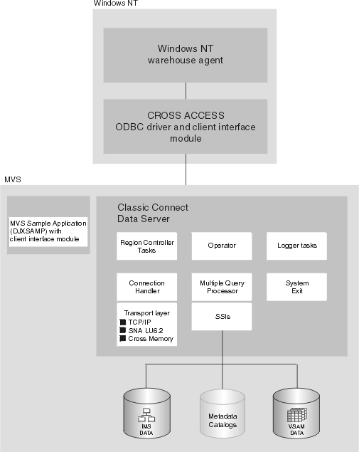
You can use Classic Connect with the Data Warehouse Center to access data in IMS and VSAM databases.
Classic Connect provides read access to nonrelational data stored in Information Management Systems (IMS(TM)) databases and Virtual Storage Access Method (VSAM) data sets on OS/390(TM). It provides communication, data access, and data mapping functions so you can read nonrelational data using relational queries.
This chapter contains the following sections:
Classic Connect allows you to access nonrelational data by issuing a standard SQL query from a Data Warehouse Center step. You access the data just as if the data was in a DB2(R) database.
Classic Connect provides read-only relational access to IMS databases and VSAM data sets. It creates a logical, relational database, complete with logical tables that are mapped to actual data in IMS or VSAM databases. Specifically:
Using this relational structure, Classic Connect interprets relational queries that are submitted by users against IMS databases and VSAM data sets.
You can define multiple logical databases for a single data source (such as a set of VSAM data sets or a single IMS database). Multiple logical tables can be defined in a logical database.
You can define multiple logical tables for a single data entity (such as a VSAM data set or an IMS segment). For example, a single VSAM data set can have multiple logical tables defined for it, each one mapping data in a new way.
Use Classic Connect with the Data Warehouse Center if your data warehouse uses operational data in an IMS or VSAM database. Use Classic Connect to map the nonrelational data into a pseudo-relational format. Then use the CROSS ACCESS ODBC driver to access the pseudo-relational data. You can then define an IMS or VSAM warehouse source in the Data Warehouse Center that corresponds to the pseudo-relational data.
Using Classic Connect with the Data Warehouse Center consists of the following major components:
Figure 24 shows how Classic Connect and its components fit into the overall Data Warehouse Center architecture.
Figure 24. Classic Connect architecture
 |
Warehouse agents manage the flow of data between the data sources and the target warehouses. The warehouse agents use the CROSS ACCESS ODBC Driver to communicate with Classic Connect.
The Open Database Connectivity (ODBC) interface enables applications to use Structured Query Language (SQL) statements to access data in relational and nonrelational database management systems.
The ODBC architecture consists of four components:
The Driver Manager and the driver act as one unit that processes ODBC function calls.
All data access is performed by Classic Connect data servers. A data server is responsible for the following functions:
A Classic Connect data server accepts connection requests from the CROSS ACCESS ODBC driver and the sample application on OS/390.
There are five types of services that can run in the data server:
The primary component of a data server is the region controller. The region controller is responsible for starting, stopping, and monitoring all of the other components of the data server. These different components are referred to as services. The services are implemented as individual load modules running as separate OS/390 tasks within the data server address space. Services can have multiple instances, and each instance can support multiple users.
The region controller determines which services to start based on SERVICE INFO ENTRY parameter settings.
Included in the region controller service is the OS/390 Master Terminal Operator (MTO) interface, which allows you to display and control the services and users that are being serviced by a data server. Using the MTO interface, you can also dynamically configure the data server.
Initialization services are special tasks that are used to initialize and terminate different types of interfaces to underlying database management systems or OS/390 system components. Currently, three initialization services are provided:
A connection handler (CH) service task is responsible for listening for connection requests from the Data Warehouse Center. Connection requests are routed to the appropriate query processor task for subsequent processing.
Classic Connect supplies three typical transport layer modules that can be loaded by the CH task:
The OS/390 client application, DJXSAMP, can connect to a data server using any of these methods; however, the recommended approach for local clients is to use OS/390 cross memory services. the Data Warehouse Center can use either TCP/IP or SNA to communicate with a remote data server.
The query processor is the component of the data server that is responsible for translating client SQL into database- and file-specific data access requests. The query processor treats IMS and VSAM data as a single data source and is capable of processing SQL statements that access either IMS, VSAM, or both. Multiple query processors can be used to separately control configuration parameters, such as those that affect tracing and governors, to meet the needs of individual applications.
The query processor can service SELECT statements. The query processor invokes one or more subsystem interfaces (SSIs) to access the target database or file system referenced in an SQL request. The following SSIs are supported:
Classic Connect supplies a RUNSTATS utility program that is used to update population statistics for the logical tables and their associated indexes and keys. This information can be used by the query processor to optimize JOINs.
A logger service is a task that is used for system monitoring and trouble shooting. A single logger task can be running within a data server. During normal operations, you will not need to be concerned with the logger service.
The enterprise server is an optional component that you can use to manage a large number of concurrent users across multiple data sources. An enterprise server contains the same tasks that a data server uses, with the exception of the query processor and the initialization services.
Figure 25 shows how the enterprise server fits into a Classic Connect configuration:
Figure 25. Classic Connect architecture with the enterprise server implemented
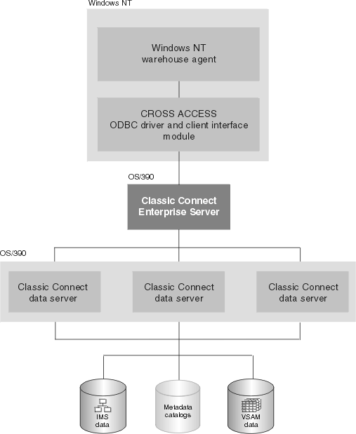 |
Like a data server, the enterprise server's connection handler is responsible for listening for client connection requests. However, when a connection request is received, the enterprise server does not forward the request to a query processor task for processing. Instead, the connection request is forwarded to a data source handler (DSH) and then to a data server for processing. The enterprise server maintains the end-to-end connection between the client application and the target data server. It is responsible for sending and receiving messages between the client application and the data server.
The enterprise server is also used to perform load balancing. Using configuration parameters, the enterprise server determines the locations of the data servers that it will be communicating with and whether those data servers are running on the same platform as the enterprise server.
The enterprise server can automatically start a local data server if there are no instances active. It can also start additional instances of a local data server when the currently active instances have reached the maximum number of concurrent users they can service, or the currently active instances are all busy.
The Classic Connect nonrelational data mapper is a Microsoft(R) Windows(R)-based application that automates many of the tasks required to create logical table definitions for nonrelational data structures. The objective is to view a single file or portion of a file as one or more relational tables. The mapping must be accomplished while maintaining the structural integrity of the underlying database or file.
The data mapper interprets existing physical data definitions that define both the content and the structure of nonrelational data. The tool is designed to minimize administrative work, using a definition-by-default approach.
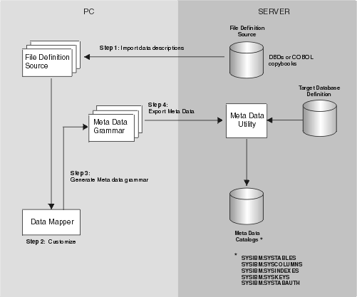
The data mapper accomplishes the creation of logical table definitions for nonrelational data structures by creating metadata grammar from existing nonrelational data definitions (COBOL copybooks). The metadata grammar is used as input to the Classic Connect metadata utility to create a metadata catalog that defines how the nonrelational data structure is mapped to an equivalent logical table. The metadata catalogs are used by query processor tasks to facilitate both the access and translation of the data from the nonrelational data structure into relational result sets.
The data mapper import utilities create initial logical tables from COBOL copybooks. A visual point-and-click environment is used to refine these initial logical tables to match site- and user-specific requirements. You can utilize the initial table definitions automatically created by data mapper, or customize those definitions as needed.
Multiple logical tables can be created that map to a single physical file or database. For example, a site may choose to create multiple table definitions that all map to an employee VSAM file. One table is used by department managers who need access to information about the employees in their departments; another table is used by HR managers who have access to all employee information; another table is used by HR clerks who have access to information that is not considered confidential; and still another table is used by the employees themselves who can query information about their own benefits structure. Customizing these table definitions to the needs of the user is not only beneficial to the end-user but recommended.
Figure 26 shows the data administration workflow with data mapper.
Figure 26. Data mapper workflow
 |
The data mapper contains embedded FTP support to facilitate file transfer from and to the mainframe.
The steps in Figure 26 are described as follows:
The data mapper creates default logical table definitions from the COBOL copybook information. If these default table definitions are acceptable, skip the following step and go directly to step 3.
After completing these steps, you are ready to use Classic Connect operational components with your tools and applications to access your nonrelational data.
This section summarizes the requirements for setting up integration between Classic Connect and the Data Warehouse Center.
The integration requires the following software:
Optionally, you can the DataJoiner Classic Connect data mapper to generate metadata grammar for you. You can obtain the data mapper from the following Web site:
http://www.software.ibm.com/data/datajoiner/news.html#newcxa
Complete the tasks summarized in Table 33 to set up integration between Classic Connect and the Data
Warehouse Center. See the documentation listed in each task for more
information.
Table 33. Summary of installation and configuration tasks
| Task | Content | Location |
| Learning about the integration | What is Classic Connect? | What is Classic Connect? |
| Concepts and terminology | Chapter 2 of DataJoiner Classic Connect: Installation, Configuration, and Reference Guide | |
| Installing and configuring the data server | System requirements and planning | Chapter 3 of DataJoiner Classic Connect: Installation, Configuration, and Reference Guide |
| Installing Classic Connect on OS/390 | Chapter 4 of DataJoiner Classic Connect: Installation, Configuration, and Reference Guide | |
| Data server installation and verification procedure | Chapter 6 of DataJoiner Classic Connect: Installation, Configuration, and Reference Guide | |
| Introduction to data server setup | Chapter 6 of DataJoiner Classic Connect: Installation, Configuration, and Reference Guide | |
| Configuring communication protocols between OS/390 and Windows NT | Configuring communications protocols between OS/390 and Windows NT(R) | |
| Installing and configuring the client workstation | Configuring a Windows NT client | Configuring a Windows NT client |
| Defining an agent site | Defining agent sites | |
| Using an IMS or VSAM warehouse source | Mapping nonrelational data and creating queries | Chapter 13 of DataJoiner Classic Connect: Installation, Configuration, and Reference Guide and DataJoiner Classic Connect: Data Mapper Installation and User's Guide |
| Optimization | Chapter 14 of DataJoiner Classic Connect: Installation, Configuration, and Reference Guide | |
| Defining a warehouse source | Defining a non-DB2 database warehouse source in the Data Warehouse Center | |
| Migrating from the Visual Warehouse Host Adapters | Migrating from the Visual Warehouse Host Adapters to Classic Connect | Migrating from the Visual Warehouse Host Adapters to Classic Connect |
Classic Connect supports the TCP/IP and SNA LU 6.2 (APPC) communication protocols to establish communication between a Visual Warehouse agent and Classic Connect data servers. A third protocol, cross memory, is used for local client communication on OS/390.
This chapter describes modifications you need to make to the TCP/IP and SNA communications protocols before you can configure Classic Connect and includes the following sections:
Classic Connect supports the following communications options:
Cross memory should be used to configure the local OS/390 client application (DJXSAMP) to access a data server. Unlike for SNA and TCP/IP, there are no setup requirements to use the OS/390 cross memory interface. This interface uses OS/390 data spaces and OS/390 token naming services for communications between client applications and data servers.
Each cross memory data space can support up to 400 concurrent users, although in practice this number may be lower due to resource limitations. To support more than 400 users on a data server, configure multiple connection handler services, each with a different data space name.
The following example illustrates the communications compound address field:
XM1/DataSpace/Queue
Because you don't need to modify any cross memory configuration settings, this protocol is not discussed in detail here.
SNA is a more sophisticated protocol and supports hardware compression, which can greatly reduce the amount of data actually transmitted over the wire. Unfortunately, the infrastructure requirements and setup time for using SNA are generally more expensive than using TCP/IP.
A single TCP/IP connection handler service can service a maximum of 255 concurrent users. Depending on your particular TCP/IP subsystem, further limitations might apply.
Multiple sessions are created on the specified port number. The number of sessions carried over the port is the number of concurrent users to be supported plus one for the listen session the connection handler uses to accept connections from remote clients. If the TCP/IP implementation you are using requires you to specify the number of sessions that can be carried over a single port, you must ensure that the proper number of sessions have been defined. Failure to do so will result in a connection failure when a client application attempts to connect to the data server.
This section describes the steps you must perform, both on your OS/390 system and on your Windows NT system, to configure a TCP/IP communications interface for Classic Connect. This section also includes a TCP/IP planning template and worksheet that are designed to illustrate TCP/IP parameter relationships.
There are two types of TCP/IP CIs that function with Classic Connect: IBM's TCP/IP and Berkeley Sockets. Your configuration may differ depending on which type of TCP/IP CI you are using. If your site does not use TCP/IP, proceed to Configuring the LU 6.2 communications protocol.
Both interfaces allow Classic Connect to communicate with the OS/390 TCP/IP stack. Berkeley Sockets allows you to use the host and service name, where IBM's TCP/IP requires a numeric IP address and port number. Berkeley Sockets can use a local host file instead of calling DNS. However, both Berkeley Sockets and IBM's TCP/IP require a TCP/IP address space name.
Classic Connect's TCP/IP is compatible with both IBM's and Interlink's Berkeley Socket TCP/IP. This section describes how to configure Classic Connect using IBM's TCP/IP. For more detailed information about IBM's or Interlink's TCP/IP, refer to the appropriate product's documentation.
Berkeley sockets is supported by IBM and Interlink. The Berkeley Sockets version requires an additional parameter in the DJXDSCF member called TASK PARAMETER, which identifies the Interlink subsystem name and identifies the location of the configuration data sets for IBM. Within the configuration data sets, users must specify the name of the started-task procedure used to start the TCP/IP address space name and can also specify the TCP/IP DNS IP addresses. If no environment variables are passed, then the default value TCPIP is used for both the address space name and as the high-level qualifier (hlq) of the standard configuration files:
Classic Connect uses a search order to locate the data sets, regardless of whether Classic Connect sets the hlq or not.
Determine the following values for the OS/390 system on which Classic Connect is being installed, and enter these values in the worksheet portion of Figure 27.
Obtain either the hostname or IP address of the OS/390 system.
Using a hostname requires the availability of a configured local HOSTS file or a domain name server. If a domain name server is involved, then there is some overhead required to resolve the HOST name to the correct IP address. However, it is recommended that you use hostnames in remote client configuration files for readability and ease of future configuration changes.
Using hostnames also makes it easier to change IP addresses if the environment changes. If hostnames are used, frequently the data server/remote clients will not have to be reconfigured. Classic Connect can be brought down, and the network administrator can change the IP address for a hostname in the OS/390 and client domain name server(s). When the data server is restarted it will automatically listen on the new IP address for connection requests from remote clients. When a remote client connects to the data server it will automatically use the new IP address that has been assigned to the hostname without a change to the Classic Connect configuration files.
For IBM's TCP/IP, determine the IP address or hostname of the host computer on which Classic Connect is being installed. If you are running your OS/390 TCP/IP on off-loaded devices, specify the address of the TCP/IP stack on the OS/390 image, not the address of an off-load gateway's IP stack.
Obtain a unique port (socket) number greater than 1024 for each data server that will be accessed from a client.
The port number cannot be the same as any port that is already defined for use by any other application, including other Classic Connect data servers on the same OS/390 system. Using a non-unique port number causes the data server to fail at start up. To determine if a port number has already been assigned to another application, issue the following command from the Spool Display and Search Facility (SDSF) log:
TSO NETSTAT SOCKETS
Because some sites restrict the use of certain port numbers to specific applications, you should also contact your network administrator to determine if the port number you've selected is unique and valid.
Optionally, you can substitute the service name assigned to the port number defined to your system.
Service names, addresses, and tuning values for IBM's TCP/IP are contained in a series of data sets:
where "hlq" represents the high-level qualifier of these data sets. You can either accept the default high-level qualifier, TCPIP, or you can define a high-level qualifier specifically for Classic Connect.
When you have determined these values, use Figure 27 to complete the OS/390 configuration of your TCP/IP communications.
You must configure your Windows NT machine to locate the data server on OS/390.
If you are using the IP address in the client configuration file, you can skip this step.
The client workstation must know the address of the host server to which it is attempting to connect. There are two ways to resolve the address of the host:
If you are already using a name server on your network, proceed to step 2.
Add an entry to the HOSTS file on the client for the server's hostname as follows:
9.112.46.200 stplex4a # host address for Classic Connect
where 9.112.46.200 is the IP address, and stplex4a is the HOSTNAME. If the server resides in the same Internet domain as the client, this name can be a flat hostname. If the server is not in the same domain, the name must be a fully-specified domain name, such as stplex4a.stl.ibm.com, where stl.ibm.com is an example of a domain name.
Notes:
If you are using the port number in the client configuration file, you can skip this step.
The following information must be added to the SERVICES file on the client for TCP/IP support:
ccdatser 3333 # CC data server on stplex4a
The SERVICES file is located in the %SYSTEMROOT%\SYSTEM32\DRIVERS\ETC directory.
The left side of Figure 27 provides you with an example set of TCP/IP values for an OS/390 configuration; these values will be used during data server and client configuration in a later step. Use the right side of the figure as a template in which to enter your own values.
Figure 27. TCP/IP Communications Template and Worksheet
 |
This section describes the values you must determine and steps you must perform, both on your OS/390 system and on your Windows NT system, to configure LU 6.2 (SNA/APPC) communications for Classic Connect.
The information in this section is specific to Microsoft SNA Server Version 3.0. For more information about configuring Microsoft SNA Server profiles, see the appropriate product documentation. This section also includes a communications template and worksheet that are designed to clarify LU 6.2 parameter relationships on OS/390 and Windows NT and assist you with your LU 6.2 configuration.
If you will be using LU 6.2 to access Classic Connect from DataJoiner, you need to configure VTAM(R) table definitions on your OS/390 system, which include:
The Application ID must be unique for a data server. Using a non-unique value causes the data server to fail at start up.
Unlike TCP/IP, you can specify the packet size for data traveling through the transport layer of an SNA network. However, this decision should be made by network administrators because it involves the consideration of complex routes and machine/node capabilities. In general, the larger the bandwidth of the communications media, or pipe, the larger the RU size should be.
This section explains the values you need to configure to use the SNA LU 6.2 protocol with your Windows NT client.
For each Windows NT system, configure the following values:
This example assumes you have installed a SNA DLC 802.2 link service. See your network administrator to obtain local and remote node information.
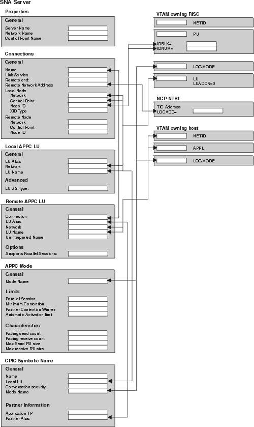
The LU name and network must match the local node values in the Connections for the SNA Server profile. The LU must be an Independent LU type.
There must be one of these profiles for each Classic Connect data server or enterprise server that will be accessed. It must support parallel sessions. It will match the Application ID configured in VTAM table definitions on OS/390 discussed in Configuring LU 6.2 on OS/390.
See the mode, CX62R4K in Figure 28. It has a maximum RU size of 4096.
There must be one of these for each Classic Connect data server or enterprise server that will be accessed. The TP Name referenced in this profile must be unique to the Classic Connect data server or enterprise server on a given OS/390 system.
After you have entered these values, save the configuration, and stop and restart your SNA Server. When the SNA Server and the Connection (in this example, OTTER and SNA OS/390 respectively), are 'Active,' the connection is ready to test with an application.
Figure 28, which provides you with an example set of VTAM and SNA values, is included for reference. Use Figure 29, which is a duplicate of Figure 28 without the supplied values, as a worksheet in which you can enter the VTAM and SNA values specific to your LU 6.2 configuration. You will need the values you enter in this worksheet to complete configuration steps in subsequent chapters.
Figure 28. LU 6.2 Configuration Template
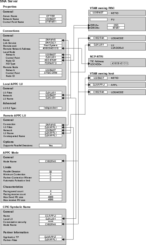 |
Figure 29. LU 6.2 Configuration Worksheet
 |
This section describes how to install the CROSS ACCESS ODBC driver, and use the driver to configure data sources.
The CROSS ACCESS ODBC driver is installed automatically with the Data Warehouse Center. Select the warehouse server or the Windows NT warehouse agent.
CROSS ACCESS ODBC data sources are registered and configured using the ODBC Administrator. Configuration parameters unique to each data source are maintained through this utility.
You can define many data sources on a single system. For example, a single IMS system can have a data source called MARKETING_INFO and a data source called CUSTOMER_INFO. Each data source name should provide a unique description of the data.
The following information must be available before you attempt to configure the ODBC driver. If you are missing any of this information, see your system administrator.
Before you configure the ODBC driver, be sure that the Windows client is set up for the connection handler that you want to use, either TCP/IP or LU 6.2.
For APPC connectivity between Classic Connect and DataJoiner for Windows NT, you need Microsoft SNA Server Version 3 service pack 3 or later.
The data sources that are defined for all the currently installed ODBC drivers are listed in the ODBC Data Source Administrator window. From this window, you can:
To open the ODBC Data Source Administrator window:
Figure 30. ODBC Data Source Administrator window
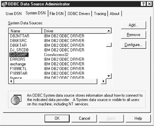 |
This window displays a list of data sources and drivers on the System DSN page.
To add and configure a data source:
Figure 31. Create New Data Source window
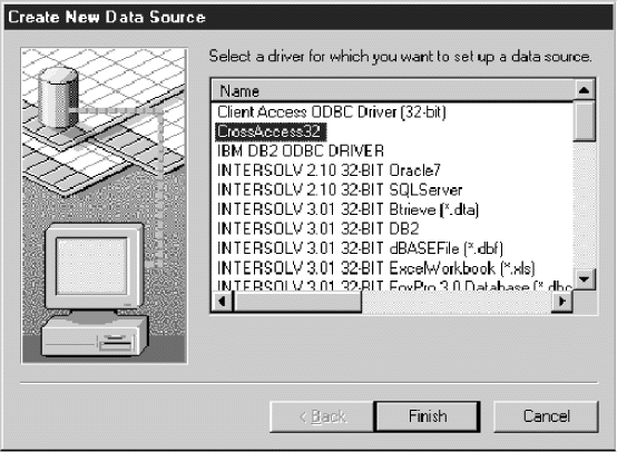 |
Figure 32. Communications Protocol window
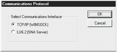 |
In this window, you can enter parameters for new data sources or modify parameters for existing data sources. Many of the parameters must match the values specified in the server configuration. If you do not know the settings for these parameters, contact the Classic Connect system administrator.
The parameters that you enter in this window vary depending on whether you are using the TCP/IP or LU 6.2 communications interface.
Use the CROSS ACCESS ODBC Data Source Configuration window to:
Figure 33. The CROSS ACCESS ODBC Data Source Configuration window for TCP/IP
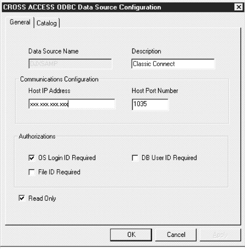 |
To configure TCP/IP communications:
Use the Catalog page to perform the following tasks:
To set the database catalog options:
Figure 34. CROSS ACCESS ODBC Data Source Configuration window
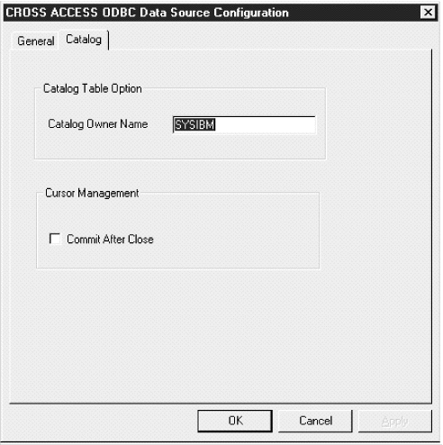 |
If you leave this box clear, the cursors are freed without issuing a COMMIT call.
The TCP/IP communications information is saved.
Use the CROSS ACCESS ODBC Data Source Configuration window to:
Figure 35. The CROSS ACCESS ODBC Data Source Configuration window for LU 6.2
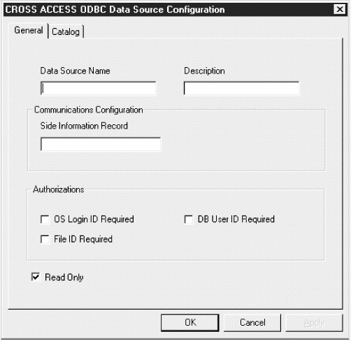 |
To configure LU 6.2 communications:
The SIR name refers to a side information record (also called a CPIC symbolic name in Figure 29) defined in the SNA server. This SIR must include the configuration parameters that represent the data server.
Use the Catalog page to perform the following tasks:
To set the database catalog options:
Figure 36. Database Catalog Options window
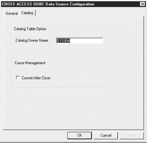 |
If you leave this box clear, the cursors are freed without issuing a COMMIT call.
The LU 6.2 communications information is saved.
The CROSS ACCESS ODBC driver maintains a set of configuration parameters common to all CROSS ACCESS data sources. Configuration of these parameters are performed in the CROSS ACCESS Administrator window. The following steps show how to configure the ODBC driver parameters.
Figure 37. General page of the CROSS ACCESS Administrator window
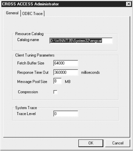 |
The language catalog contains messages in a specific language and is pointed to by a file contained within the CROSS ACCESS configuration files.
This value tunes message blocking by controlling the amount of data that is returned in a single fetch request. The system packs as many rows of data as possible into a fetch buffer of the size specified. For example, if the fetch buffer is set to 10,000 bytes and each row is 2,000 bytes, the system can pack 5 rows per fetch request. If a single row is returned but does not fit into the specified buffer, the fetch buffer internally increases to fit the single row of data. To turn off message blocking, set this parameter to 1. The value must be from 1 to 64,000, inclusive. The default value is 10,000.
You can specify the following time intervals:
Specify a value between 0 and 1000MS, 60S, or 60M. The default value is 6M.
Specify the number in bytes. The actual workable maximum value should be set to 2 MB less than the heap size. If the value specified is less than 1 MB, 1 MB is used. If the amount of storage that can be obtained is less than the value specified, the maximum amount available is obtained. The maximum permitted value is 2,097,152,000 bytes (2 GB). The default value is 1,048,575 bytes (1 GB).
Figure 38. ODBC Trace page of the CROSS ACCESS Administrator window
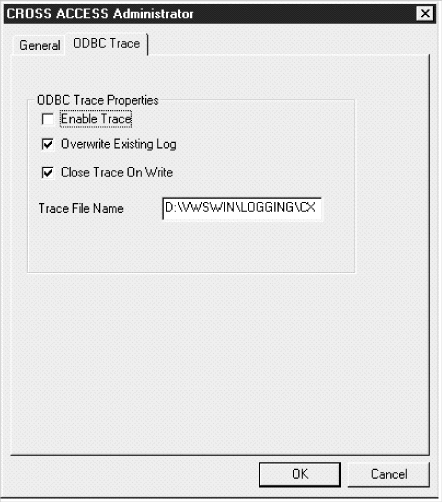 |
If the directory is not indicated, the trace file will be created in the subdirectory of the Program Files directory that corresponds to the tool that issued the query to the ODBC data source.