Best Practices for the Common
Base Event and
Common Event Infrastructure
Guidelines for Using IBM's Initial Implementation of the
WSDM Event Format
�Note: Before using this information and the
product it supports, read the information �Notices� on page 120.
� Copyright International Business
Machines Corporation 2006. All rights reserved.
US Government Users
Restricted Rights - Use, duplication or disclosure restricted by GSA ADP
Schedule Contract with IBM Corp.
Table
of contents. 3
1����� About this guide. 7
1.1������ Purpose. 7
1.2������ Scope. 8
1.3������ Who should read this
guide. 8
1.4������ Background. 8
1.4.1����� What is autonomic computing?. 8
1.4.2����� What is an event?. 10
1.4.3����� What is problem determination?. 11
1.4.4����� Problem determination phases. 11
1.4.5����� What is a problem determination
event?. 12
1.4.6����� What is a business event?. 13
1.4.7����� The Common Base Event 13
1.4.7.1������� When should I use Common Base
Events?. 14
1.4.7.2������� How do I choose between using
Common Base Event and ARM?. 14
1.4.7.3������� How does the Common Base Event
relate to other existing formats?. 14
1.4.7.4������� Who directs the Common Base Event
Initiative?. 15
1.4.7.5������� How does the Common Base Event
relate to the OASIS WSDM Event Format standard?. 15
1.4.8����� What is an event infrastructure?. 16
1.4.8.1������� Common Event Infrastructure
overview.. 17
1.4.8.2������� Common Event Infrastructure
components. 18
1.4.9����� Programming model overview.. 18
1.4.9.1������� Formatting a Common Base Event
using the TPTP Common Base Event Programming Model 19
1.4.9.2������� Capturing an event using JSR-47. 21
1.4.9.2.1����� Basic
event capture using JSR-47. 22
1.4.9.2.2����� Advanced
event capture (using JSR-47) 24
1.4.9.3������� Using the CEI event emitter 25
1.4.9.4������� Advanced CEI topics. 28
1.4.9.4.1����� Event
groups, persistence, and routing. 28
1.4.9.4.2����� Consuming
events using CEI event subscription and event access. 29
1.4.9.4.3����� The CEI
relationship to the WebSphere enterprise service bus (WESB) 31
2����� Using Common Base
Events. 33
2.1������ Common Base Event
Structure. 33
2.2������ Required compared to
optional elements. 34
2.2.1����� Event requirements. 34
2.3������ The Common Base Event
core (required elements) 38
2.3.1����� version.. 38
2.3.2����� creationTime.. 39
2.3.3����� sourceComponentId and reporterComponentId.. 40
2.3.4����� Source and reporter component identification
guidelines and best practices�� 41
2.3.5����� ComponentIdentification.. 42
2.3.5.1����� Component identification concepts and usage.. 43
2.3.5.1.1������������ Component structure model.. 43
2.3.5.1.2������������ Component deployment model.. 44
2.3.5.1.3������������ How the models are represented in the Common Base Event.. 45
2.3.5.2����� location.. 45
2.3.5.3����� locationType.. 46
2.3.5.4����� application.. 47
2.3.5.5����� component.. 47
2.3.5.6����� componentIdType.. 48
2.3.5.7����� componentType.. 48
2.3.5.8����� subComponent.. 49
2.3.5.9����� executionEnvironment.. 49
2.3.5.10��� instanceId.. 50
2.3.5.11��� processId.. 50
2.3.5.12��� threadId.. 51
2.3.6����� situation.. 52
2.3.6.1����� categoryName.. 53
2.3.7����� SituationType.. 54
2.3.7.1����� reasoningScope.. 54
2.3.7.2����� StartSituation.. 55
2.3.7.2.1������������ successDisposition.. 55
2.3.7.2.2������������ situationQualifier.. 56
2.3.7.2.3������������ reasoningScope.. 56
2.3.7.3����� StopSituation.. 57
2.3.7.3.1������������ successDisposition.. 57
2.3.7.3.2������������ situationQualifier.. 57
2.3.7.3.3������������ reasoningScope.. 57
2.3.7.4����� ConnectSituation.. 58
2.3.7.4.1������������ successDisposition.. 58
2.3.7.4.2������������ situationDisposition.. 58
2.3.7.4.3������������ reasoningScope.. 58
2.3.7.5����� ConfigureSituation.. 59
2.3.7.5.1������������ successDisposition.. 59
2.3.7.5.2������������ reasoningScope.. 59
2.3.7.6����� RequestSituation.. 59
2.3.7.6.1������������ successDisposition.. 60
2.3.7.6.2������������ situationQualifier.. 60
2.3.7.6.3������������ reasoningScope.. 60
2.3.7.7����� FeatureSituation.. 61
2.3.7.7.1������������ featureDisposition.. 61
2.3.7.7.2������������ reasoningScope.. 61
2.3.7.8����� DependencySituation.. 62
2.3.7.8.1������������ dependencyDisposition.. 62
2.3.7.8.2������������ reasoningScope.. 62
2.3.7.9����� AvailableSituation.. 63
2.3.7.9.1������������ operationDisposition.. 63
2.3.7.9.2������������ availabilityDisposition.. 63
2.3.7.9.3������������ processingDisposition.. 64
2.3.7.9.4������������ reasoningScope.. 64
2.3.7.10��� CreateSituation.. 65
2.3.7.10.1���������� successDisposition.. 65
2.3.7.10.2���������� reasoningScope.. 65
2.3.7.11��� DestroySituation.. 66
2.3.7.11.1���������� successDisposition.. 66
2.3.7.11.2���������� reasoningScope.. 66
2.3.7.12��� ReportSituation.. 67
2.3.7.12.1���������� reportCategory.. 67
2.3.7.12.2���������� reasoningScope.. 68
2.3.7.13��� OtherSituation.. 68
2.3.8����� Required and optional elements.. 68
2.4������ The remainder of the
Common Base Event (optional, but important, elements) 69
2.4.1����� localInstanceId.. 69
2.4.2����� globalInstanceId.. 70
2.4.3����� severity.. 70
2.4.4����� priority.. 72
2.4.5����� extensionName.. 73
2.4.6����� Aggregating events (repeatCount and
elapsedTime properties).. 74
2.4.6.1����� repeatCount.. 74
2.4.6.2����� elapsedTime.. 74
2.4.7����� sequenceNumber.. 74
2.4.8����� Messages (msg and msgDataElement).. 75
2.4.8.1����� Models for handling message
internationalization.. 75
2.4.8.2����� msg.. 77
2.4.8.3����� msgDataElement.. 78
2.4.8.4����� msgId.. 79
2.4.8.5����� msgIdType.. 79
2.4.8.6����� msgLocale.. 80
2.4.8.7����� msgCatalogId.. 80
2.4.8.8����� msgCatalog.. 80
2.4.8.9����� msgCatalogType.. 80
2.4.8.10��� msgCatalogTokens.. 81
2.4.9����� ContextDataElement.. 82
2.4.9.1����� type.. 83
2.4.9.2����� name.. 83
2.4.9.3����� contextValue.. 83
2.4.9.4����� contextId.. 84
2.4.10������� ExtendedDataElement.. 85
2.4.10.1��� name.. 86
2.4.10.2��� type.. 88
2.4.10.3��� values.. 89
2.4.10.4��� hexValue.. 89
2.4.10.5��� children.. 89
2.4.11������� AssociatedEvents.. 90
2.4.11.1��� associationEngine.. 91
2.4.11.2��� associationEngineInfo.. 92
2.4.11.3��� resolvedEvents.. 92
2.4.12������� AssociationEngine.. 93
2.4.12.1��� name.. 93
2.4.12.2��� type.. 94
2.4.12.3��� id.. 94
3����� Scenarios. 95
3.1������ Problem determination
event scenario. 95
3.2������ Business event
scenario. 96
3.2.1����� Insurance claim process. 97
3.2.1.1������� Understanding the current business process and
making improvements. 97
3.2.1.2������� Monitoring the business process. 98
3.2.1.3������� Understanding business objects and resources. 99
3.2.2����� Business event categories. 101
3.2.2.1������� Business activity event 102
3.2.2.2������� Business situation event 102
3.2.3����� Business event design. 102
3.2.3.1������� Business activity event 103
3.2.3.1.1����� Business activity event content 103
3.2.3.1.2����� Business activity event reporting. 104
3.2.3.1.3����� Business activity event consumption. 105
3.2.3.2������� Business situation event 105
3.2.3.2.1����� Business situation event content 105
3.2.3.2.2����� Business situation event reporting. 107
3.2.3.2.3����� Business situation event Consumption. 108
3.3������ Bridging IT and
business events. 108
3.3.1����� Problem description. 108
3.3.1.1������� Physical topology. 110
3.3.1.2������� Components and implementation flow.. 110
3.3.1.3������� Event data. 111
4����� References. 113
4.1������ Cited references. 113
4.2������ Other related reading. 113
This
chapter provides an introduction to the Common Base Event version 1.0.1 best practices
guide. The purpose, scope and intended audience for this document are
presented. Background information, including autonomic computing concepts, the
Common Base Event and the Common Event Infrastructure is also introduced.
The technology used for business
applications continues to become more complex as businesses continue to rely
more heavily on their information technology (IT) infrastructure. Autonomic
computing is intended to reduce the impact of this added complexity by enabling
these systems to manage themselves. One of the critical first principles
required for this common management is that each component and subsystem must
represent itself in a common way. Specifically, information that describes situations
that arise, as well as the state of the components at any time, must be
accessible in a common language, a lingua franca. This is the only way
that common management components are able to reliably interpret and act on the
information provided to them. The use of this common event format extends
beyond management of the IT infrastructure to occurrences that are used to
manage business processes (so-called business events, which are detailed
later).
The Web Services Distributed Management (WSDM) standard
resulted from a collaborative industry effort. WSDM was approved by the
Organization for the Advancement of Structured Information Standards (OASIS).
The standard provides the foundation for enabling the use of Web services to
build management applications, offering one set of instrumentation to manage
resources. WSDM is an important milestone in the evolution of systems
management. Coupled with virtualization technology, the WSDM standard enables
self-managing autonomic systems and service-oriented architecture (SOA)-based
management.
As part of the WSDM standard,
OASIS ratified the WSDM Event Format (WEF), which defines a common format for
events that contains extension points that allow additional semantic
information to be included. The Common Base Event is IBM�'s initial implementation of WEF. Because Common Base Events
utilize many of the same concepts as WEF, many of the best practices outlined
in this document will facilitate migration to WEF.
In addition to providing software
for developers to take advantage of the standard, IBM has� Tivoli� products, WebSphere� software, DB2�
software and systems virtualization products available today that include
implementations of WSDM, with more planned in the future. For more information about IBM�s activities with the WSDM standard,
visit www.ibm.com/autonomic/wsdm.
The goal of the Common Base Event is to
provide such a standard event format, and the purpose of this document is to
supplement the Common Base Event specification (CBE101) by providing additional
information about the usage of the Common Base Event.
The Common
Base Event addresses two issues of notification diversity: the format and the
content used to represent situations. This document offers practical how-to
information for Common Base Events. It provides guidance about the generation
and consumption of Common Base Events, including how to populate and interpret
certain key elements of those events in a consistent and meaningful manner.
This
document is part of the Common Base Event library and is intended to supplement
the Common Base Event specification (CBE101).
This document does not supplant the Common Base Event
specification [CBE101], which is considered prerequisite reading. That
specification is the authoritative source for information about Common Base
Events. This guide is a companion document that describes best practices,
conventions, and guidelines for the generation and use of Common Base Events. This
guide not only provides general information, but also provides
information related to specific applications for the Common Base Event,
including:
�
How to use Common Base Events in general
�
How to use Common Base Events specifically for
problem determination applications
�
How to use Common Base Events specifically for
events related to business activities
�
How to use certain programming environments to
create and transmit Common Base Events
�
How to use the Common Event Infrastructure to
transport events
The primary audience for this guide includes developers who
will be creating tools or infrastructure to generate or work with Common Base
Events, as well as developers who need to create the events themselves. Others
who want to better understand how Common Base Events can be used will also be
interested.
This section addresses
autonomic computing concepts and introduces the autonomic computing
architecture. See [ACBP] for further details about the autonomic computing
architecture.
The
overarching goal of autonomic computing is to shift the burden of
managing IT systems from IT professionals to the systems themselves. The term
comes from the autonomic nervous system of the human body, the system that
regulates your body�s basic functions without your conscious awareness. For
instance, when you need to run to catch a train, you don�t need to consciously
decide to produce adrenaline, reallocate oxygen to the muscles in your legs,
and increase your heart rate. Those important and necessary physical
adjustments are handled for you automatically. In a similar way, self-managing autonomic
systems handle more and more tasks on their own behalf, minimizing the need for
intervention on the part of the IT staff. Autonomic computing behavior is
necessary for building effective on demand operating environments that adapt
and adjust quickly to the changing computing needs of organizations.
The
Common Base Event is one fundamental enabler for self-managing autonomic
systems. As described in this document, Common Base Events can be used to
communicate situations that arise throughout the IT system.
The Autonomic
Computing Architectural Blueprint (ACBP) provides this overview of the
autonomic computing architecture:
The autonomic computing architecture organizes an
autonomic computing system into the layers and parts shown in Figure 1
Autonomic computing reference architecture.
These parts are connected using enterprise service bus patterns that allow the
components to collaborate using standard mechanisms such as Web services. The
enterprise service bus integrates the various blueprint building blocks, which
include: �touch points for managed
resources, knowledge sources, and autonomic managers.

Figure 1 Autonomic computing reference
architecture
The lowest layer contains the
system components, or managed resources, that make up the IT
infrastructure. These managed resources can be any type of resource (hardware
or software) and may have embedded self-managing attributes. The next layer
incorporates consistent, standard manageability interfaces for accessing and
controlling the managed resources. These standard interfaces are delivered
through a touch point. Layers three and four automate some portion of
the IT process using an autonomic manager. A particular resource may have one
or more touchpoint autonomic managers, each implementing a relevant control
loop. Layer three in Figure 1 Autonomic computing reference architecture
illustrates this by depicting an autonomic manager for the four broad
categories [of self-management] (self-configuring, self-healing,
self-optimizing and self-protecting). Layer four contains autonomic managers
that orchestrate other autonomic managers. It is these orchestrating autonomic
managers that deliver the system wide autonomic computing capability by
incorporating control loops that have the broadest view of the overall IT
infrastructure. The top layer illustrates a manual manager that provides a
common system management interface for the IT professional using an integrated
solutions console. The various manual and autonomic manager layers can obtain
and share knowledge via knowledge sources.
Common Base Events can be used to communicate across the
various layers of a self-managing autonomic system. This guide describes how
Common Base Events can be used to send information (such as problem
determination events) from touchpoints to touchpoint autonomic managers, how
Common Base Events can be used to communicate information (such as business
events) to orchestrating autonomic managers, and so on.
For a
more in-depth discussion of the autonomic computing architecture, see The Common Base Event on page 13.
Fundamentally, an event is an indication of an occurrence � an
indication that something of potential interest has happened. According to the
Common Base Event specification (CBE101), �Events are external, visible
manifestations of all systems operations � they represent the onset, evolution,
and conclusion of processes both large and small�. These systems and processes
are broad in scope, including everything from hardware and software in the IT
infrastructure to business processes and application orchestration. In the IT infrastructure,
events typically represent state changes in a resource, an autonomic manager,
or another component involved in the management system. In a business process,
an event can represent a business milestone or an anomalous business situation.
Events can communicate situations such as:
�
A component has stopped or started
�
A connection has been established or broken
�
A failure has occurred
�
A state transition for a task or activity in a
business process has occurred
�
An amount for a transaction has exceeded an automatic
approval threshold
The Common Base Event enables information about situations
to be captured and represented in a consistent format. The Common Base Event
format facilitates effective intercommunication among disparate components for
events that express information about logging, management, problem determination,
business processes, and other happenings in an IT system.
For the purposes of this guide, the following definitions
apply:
�
Occurrence: a happening or phenomenon
�
Situation: a classification of an
occurrence that specifies what type of an occurrence has happened
�
Event: an indication of the situation
that provides information about the situation
Although the Common Base Event is generally applicable to many
types of situations, it is useful to discuss certain categories of events
commonly encountered in IT systems. The following sections detail two such
categories: problem determination events and business events.
Problem
determination is the detection and diagnosis of situations that affect the
operational status or availability of business applications. The overarching
goal of problem determination is to maximize business and IT system availability
by minimizing the time it takes to recover from situations that affect system availability.
This is accomplished by providing the information and tools required to quickly
detect meaningful events and conditions, diagnose the underlying problem or
situation, and apply available knowledge to restore normal business and IT
system operations.
Maintaining
and restoring the availability and normal operations of a business application
is a multistep process that can be divided into the following phases:
Problem
detection (what?)
The detection and identification of situations that
adversely affect the normal operations or availability of a business
application. The challenge is to detect, as quickly as possible, unanticipated
changes in the status of an application and to identify events describing the
situations that led to those changes. This typically involves filtering out
insignificant information and events, focusing only on relevant situations and
the events specifically related to those situations.
Problem isolation (who and where?)
The process of determining
which component in the business application is experiencing the situation that
is affecting the overall availability of the application. A typical problem can
result in multiple events being reported by multiple components, as the problem
propagates through the system. Problem isolation focuses on identifying the
component that experienced the initial condition that caused the problem and
identifying the situation that led to that problem.
Problem
diagnosis (why?)
The process of determining why the problem occurred; that
is, determining the root cause of the problem. Problem diagnosis focuses on
identifying the situation that caused the problem. The problem could be caused
by an internal failure within the component (such as a software defect or
hardware error) or an adverse external condition that the component cannot
recover from (for example, an inappropriate configuration setting, a network
failure, or a malformed or inappropriate request).
Problem
recovery
Problem recovery focuses on what to do to restore normal
operation of a business application as quickly as possible. It involves using
knowledge to recover from the root cause of the problem and determining the
immediate actions needed to restore normal operations. Problem recovery, unlike
problem diagnosis, is not concerned with the reason why a problem occurred, but
rather about what can be done to work around the problem. For example, if a
business application is experiencing a problem accessing data, the problem
recovery action might be to recycle the database server. IT professionals
typically attempt problem recovery actions first, to restore the business
system�s normal operation using an effective workaround, and then concern
themselves with problem resolution (described next), to address the underlying
cause.
Problem
resolution
Problem resolution focuses on addressing the root cause of
a problem � that is, not only what to do to recover from the problem, but also what
can be done to prevent the problem from occurring again. For example, problem
resolution might attempt to determine not only that a database server failed,
but why it failed, and how to prevent the server from failing again (perhaps by
adjusting configuration settings or applying a software fix).
Problem
determination events are those events that are specifically intended to be used
to support the process of problem determination (described in �Problem determination
phases� on page 11). Problem determination events can incorporate many types
of data, including information about operational status, state changes, request
processing, performance metrics, or faults.
Problem
determination events are typically divided into two broad categories:
Log
events
Log events are typically reported by components of
a business solution during normal deployment and operations (that is, in
production environments). Although log events occur and are captured during
normal operation in a production environment, and hence often signify normal
occurrences in system operation, they also can be used to help identify
problems. The target audience for log events includes the users and
administrators of the components that make up the business solution, along with
the support teams and developers of the solution components. Log events
typically are the primary set of events that are available when a problem is
first detected and are used for problem detection and problem isolation, to
support problem recovery.
Diagnostic events
Diagnostic events, also
called trace events, are used to capture internal diagnostic information
about a component and typically are not reported or available during normal
deployment and operations (that is, in production environments). The target
audience for diagnostic events is the support teams and developers of the
components that make up the business solution. Diagnostic events typically are
used to diagnose problems within a component, such as a software failure,
especially when the information provided by the log events is not sufficient to
diagnose the problem. Diagnostic events are typically used for problem
diagnosis, to support problem resolution.
The preceding
definitions for log events and diagnostic events are general and are used
mainly to indicate how the data is captured, rather than to denote the actual
data content. Most events might be used in a problem determination process, but
log and diagnostic events typify problem determination events. Situations can
be captured as log events or diagnostic events, or both, depending on the
components that make up a solution. For example, performance data might be
captured within a log event, following the general usage guidelines published
in this document for log events. Detailed performance information might be
captured in diagnostic events that could be used to diagnose performance
problems.
The
Common Base Event defines the syntax and semantics of an event in a consistent
and common format to facilitate effective problem determination. For problem
determination events, this guide primarily focuses on describing how to use
Common Base Events to represent log events. Using Common Base Events for
diagnostic information is not addressed in a detailed manner, although many of
the concepts used for log events apply to diagnostic events.
Recent developments in the software industry, such as
complex event processing and business activity monitoring, have placed added
attention on the notion of business events, which are distinct from those
events that apply only to IT systems.
A business event is an indication of some occurrence that
is significant to the operation, monitoring, or management of the business. Whereas
the subject of an IT event (such as a problem determination event) might be a
resource, such as network router or a database, the subject of business event
is often an indication of something that is important in a business process,
such as a sales order, or a business entity, such as a retail store. The
primary audience for a business event typically is a line of business (LOB) role
within the company.
Note: A business user, in this context, is a role
player responsible for participating in, analyzing and managing business
operations. The role can vary widely based on the company�s scope and area of
expertise. For example, a business user could be the CEO, an insurance adjuster,
or a call center representative. The term is used here to distinguish this role
from an IT role player such as an IT administrator, developer, or architect who
traditionally works as part of the CIO�s organization within a company and who
is a primary audience for IT events, such as problem determination events.
Business
events can occur in both raw and derived forms. Sometimes raw
events do not directly correspond to a recognizable business event, but instead
are used to derive business events. For example, to monitor a �gold customer order
fulfillment� process, checking for violations of commitments to gold customers,
a company might need to monitor raw events that represent order submission and
order fulfillment, correlate the events, and compare the result to an
established performance target. Based on these raw events, a derived business
event might in turn be produced to communicate the occurrence of a violation.
Although business events have a different focus and primary
audience than IT events, the Common Base Event is suitable for communicating
both types of events. This guide describes the best practices to use for both
categories of events.
The
purpose of the Common Base Event is to facilitate the effective communication
among disparate enterprise components that support logging, management, problem
determination, autonomic computing, and On Demand Business functions in an
enterprise. The communication among these components can be either synchronous
or asynchronous, with the Common Base Event serving as a primary data format
for communication.
The
Common Base Event is a standard XML schema that can be used to indicate several
types of situations, in particular, problem determination and business events.
In all of these cases, the syntax and semantics of the data elements of the
event need to be consistent, because all of these event categories, occurring
in multiple components in a heterogeneous environment, need to be correlated.
Using log files, or events published to subscribers, most components generate
data whose interpretation requires the availability of contextual information.
Yet, this context is frequently maintained only in the minds of developers,
administrators, and business users who are intimately familiar with the
component or process that generates the event. This lack of context inhibits
programmatic interpretation of events, and hence, automation of management and
business processes. Consider the fundamental problem of parsing time stamps.
Format and granularity (for example, is a 12- or 24-hour clock used? Or are the
units milliseconds or microseconds?) both present unnecessary complexity for
the consumer of the time-stamped event. This lack of consistency applies
elsewhere. For example:
�
What is the host name of the machine on which
the event occurred?
�
Which component failed?
�
Is the component that failed on the same
physical machine as the application that is reporting it?
�
Which business process reported this event?
�
Are there multiple events that should be
interpreted as a single unit, in a certain order, or both?
Without standardization,
automated situation handling becomes difficult. Complexity increases further
when the problem occurs in a solution that is composed of multiple components
and processes. Events generated by components and processes typically are
product-unique, adhering to conventions limited to a particular application or
vendor. Without a standard, events are of little value to autonomic management
or business systems that rely on the completeness and accuracy of data to
determine an appropriate course of action to take in response to the event. The
Common Base Event definition alleviates this problem by providing a common
format to represent event information, including:
�
The identification of the component that is
reporting the situation
�
The identification of the component that is
affected by the situation (which might or might not be the same as the
component that is reporting the situation)
�
The situation itself
Properties
defined in the Common Base Event model supply information for these and other
important elements of an event. Additional event information includes time
stamps, event identifiers, component identifiers, and many other elements. This
broader scope of information encapsulates enough data to allow events to be
exchanged and interpreted in a deterministic and appropriate manner across
multiple management and business systems that consume the events, without
losing fidelity.
As a best practice, a Common
Base Event should be generated to promptly inform management components (including
humans) in the IT infrastructure about occurrences in the environment that are
noteworthy and of interest from a management perspective. Management in
this context includes management of the IT infrastructure as well as management
of the performance of the business processes that rely on the IT
infrastructure.
Application Response Measurement (ARM) is a current popular
method for collecting and representing monitoring data related to resources in
an IT environment. ARM data can be encapsulated in a Common Base Event message.
This specification does not prescribe precise guidelines for
using Common Base Events or ARM. Generally, however, Common Base Events should
be used to indicate significant situations that could affect the availability
or performance of the business system overall, whereas ARM data typically is used
to provide low level and/or relatively high volume instrumentation of an
application to determine the performance of that application. If ARM data
indicates a potential problem, then an appropriate Common Base Event should be
created based on the monitored ARM data.
Not all event sources natively generate Common Base Events
today, and the migration to the native production of Common Base Events will
occur over time. In some domains, existing formats or standards are available
and widely used (for example, SNMP traps, Systems Network Architecture [SNA]
alerts, Common Information Model [CIM] indications, Java� Management Extensions [JMX] and IBM Tivoli Event Integration
Facility). The Common Base Event was designed so that other formats can be
transformed to Common Base Events without data loss.
Until such time as components are modified to natively
generate Common Base Events, adapters can be used. IBM provides the Generic
Log Adapter technology (available from IBM developerWorks� Web site, see [DWAC]), along with adapter
rules for converting numerous existing formats to Common Base Events and
associated tooling to create additional adapter rules.
The Common Base Event initiative is driven by the Autonomic
Computing group of IBM. The Autonomic Computing group developed the
architecture specification for Common Base Events and promotes its adoption in
the industry. This guide supplements the Common Base Event specification. The
current version of the Common Base Event specification supported by IBM technologies
such as the Generic Log Adapter, Log and Trace Analyzer and Common Event
Infrastructure is Common Base Event version 1.0.1. Many of these technologies
are available from IBM developerWorks; see http://www128.ibm.com/developerworks/autonomic/overview.html.html128.ibm.com/developerworks/autonomic/overview.html
[IDWAC].].
The Web Services Distributed Management (WSDM) standard
resulted from a collaborative industry effort. WSDM was approved by the
Organization for the Advancement of Structured Information Standards (OASIS).
The standard provides the foundation for enabling the use of Web services to
build management applications, offering one set of instrumentation to manage
resources. WSDM is an important milestone in the evolution of systems
management. Coupled with virtualization technology, the WSDM standard enables
self-managing autonomic systems and service-oriented architecture (SOA)-based
management.
As part of the WSDM standard, OASIS ratified the WSDM Event
Format (WEF), which defines a common format for events that contains extension
points that allow additional semantic information to be included. The Common
Base Event is IBM's initial implementation of WEF. Because Common Base Events
utilize many of the same concepts as WEF, many of the best practices outlined
in this document will facilitate migration to WEF.
Figure 2
shows the various elements that interact with the event infrastructure to
produce or consume event information, along with their relationships, which
influence the characteristics of the programming model.

Figure 2 Event infrastructure relationships and
terminology
|
Figure 2 Event infrastructure relationships and terminology
|
|
1. Event Infrastructure
|
A set of services that
allow filtering, transmission, and routing of event information between
producers and consumers, as well as persistence and access to event data
store.
|
|
2. Event
|
Unsolicited noteworthy
information about a managed resource set for management purposes.
|
|
3. Event Producer
|
Producer of events about
managed resources that it represents or controls. Events are sent
asynchronously. Also known as Event Sources.
|
|
4. Customer Environment
|
Customer�s IT environment
supporting customer�s business
|
|
5. Management Systems (also
known as Event Consumers)
|
Consumers of event
information aiming management of customer�s businesses and the IT environment
supporting them.
|
|
6. Event Correlation
|
A set of analytics, and the
components that support the analytics: rules language, engines, and tools. These
allow the detection of event patterns, automation, filtering, and so forth.
|
|
7. Event Format
|
A well-defined, accepted,
and structured way of representing event information so that events can be
processed.
|
|
8. Managed Resources
|
IT and business resources
being managed in the customer�s IT environment.
|
The Common
Event Infrastructure (CEI) is an embeddable component, incorporated in
several IBM products, that supports reporting, persistence, distribution, and interpretation
of event data based on the Common Base Event format.
CEI
is not a product, but rather an IBM component used in several IBM products that
provides a programming model to report, persist, and consume Common Base Events,
and facilitates the sharing of event information.
An application
that uses CEI must install the CEI event server runtime components and
configure the event repository as part of its installation process. CEI
includes silent installation utilities and scripts that can be invoked by a
product installation process. CEI is composed of a set of modular components
that operate with IBM�s messaging (enterprise service bus [ESB]) and
application integration middleware (including IBM WebSphere Application Server).
Figure 3
provides an overview of the CEI components:

Figure 3 Common Event Infrastructure overview
1.4.8.2
Common Event Infrastructure components
The CEI has the following
components:
�
CEI Server is a
Java 2 Platform, Enterprise Edition (J2EE) application running in WebSphere
Application Server. The CEI server is responsible for determining
whether and how to distribute and persist events. It also handles requests from
event consumers to access the event information in the event repository. The
CEI Server provides event classification for
publication, event persistence and access to the event information in the CEI event
repository. The CEI server is the only part of CEI that requires a local WebSphere
Application Server instance.
�
CEI Emitter is a library that provides support for applications to report
events to the CEI server. The CEI Emitter can run in a container (J2EE) or as a
client of the WebSphere Application Server environment (Java 2 Platform,
Standard Edition [J2SE]). In the latter case, the CEI Emitter does not require
a local WebSphere Application Server instance, but does require the WebSphere
J2EE application client library.
�
CEI Catalog provides metadata information about events handled by CEI.
This catalog typically is not accessed by the other components in CEI. As a
best practice, event producers should share event metadata by populating the
event catalog with event definition records. Event consumers can browse or
extract from the catalog to determine the types and content of events available
for subscription. Chapter 2. �Using
Common Base Events� on page 33 provides additional details about how particular properties
of the Common Base Event are used in catalog definitions.
�
CEI Access is a client library that
provides support for event consumers to perform
synchronous event queries, event updates and purges of the event
repository.
�
CEI Helper is an optional client helper
class that helps event consumers map JMS messages into Common Base Event
objects when receiving events from JMS subscriptions.
CEI does not define a subscription interface, but rather uses standard JMS
subscription provided by any standard JMS provider, including IBM Platform
Messaging Component or IBM WebSphere MQ. The consumer also can be a J2EE or a
J2SE application.
Note that for the purposes of generating
and consuming Common Base Events, the CEI implementation requires the use of
the common programming model supplied by the Test and Performance Tools
Platform (TPTP) Eclipse project. The TPTP project includes an EventFactory implementation, helper methods to populate
events, and serialization methods to transform a Common Base Event object to
and from XML.
This section describes a
programming model used to format and capture Common Base Events. The intent is
to provide best practices for these operations, although the facilities used to
format and capture events can vary by implementation. This section includes:
�
An overview of the Common Base Event common programming
model used to create and format Common Base Events. Note that this set of interfaces
is also referred to as the TPTP common programming model, from the open
source Eclipse.org TPTP project � see
[TPTP]. Note that this set of interfaces should be used when creating Common
Base Events for use with CEI.
�
An overview of how the Common Base Event
programming model relates to the JSR-47 programming model, a programming model commonly
used to log events to a file or other event repository. This section describes
how applications can create Common Base Events using the JSR-47 interfaces.
�
Information about how application developers
should use the programming model when reporting and consuming Common Base
Events from the CEI Server, including CEI runtime characteristics that affect
or are related to the Common Base Event and CEI programming models.
The following steps are involved
when defining and capturing Common Base Events:
1.
The event producer determines that it should generate a
Common Base Event to inform management tools about a detected situation. Note
that situation detection is outside the scope of this document. Although
standard canonical situations are defined for the Common Base Event, the
mechanisms used for situation detection typically are specific to the software,
hardware, and other components that make up a solution.
2. After
it is determined that an event should be generated, the event producer creates
and formats a Common Base Event. Refer to the Common
Event Infrastructure overview on page 17 for more information.
3.
The event producer captures the event and processes it
appropriately, which typically involves persisting the event in the appropriate
event repositories (such as logging the event, perhaps using the JSR-47
interface)
or publishing the event to an event infrastructure (such as CEI),
or both. The event repository and event infrastructure perform the appropriate
processing to persist the event and generate any required notifications.
These activities involved with
generating an event are addressed in the following sections using this
structure:
1.
A component detects situations, formats the Common Base
Event and invokes the event capture runtime using the event capture interfaces
supplied by the runtime
2.
The event capture runtime processes the request
by completing the event formatting and sending the event to the appropriate
event handlers, for example, persisting the event in a log repository or
sending an event notification using an event infrastructure, such as CEI.
3.
The event infrastructure (if present) is used to
distribute the event to any number of event subscribers, including persisting
the event to the event repository for future processing, when appropriate.
1.4.9.1 Formatting a Common Base Event
using the TPTP Common Base Event Programming Model
Creating and formatting a Common Base Event includes these
steps:
1.
Creating the Common Base Event object
2.
Assigning component event-specific values in the Common
Base Event (that is, values unique to this specific Common Base Event reported
by the component)
3.
Assigning component default values in the Common Base
Event (that is, values unique to a component but common to all events reported by
the component)
4.
Assigning runtime values in the Common Base Event (that
is, setting runtime data in the Common Base Event, such as environment
information or runtime-defined default settings)
For example, consider an Enterprise JavaBean (EJB)
application that reports a failure when accessing a database. The application
supplies event-specific information, such as the database error code or the
database server name, and default information, such as the name of the
application. The underlying runtime, in this case the J2EE server, provides
runtime information such as the current process ID.
Consider a second example of a business process reporting a
sales-order approval milestone. The process runtime supplies event-specific
information, such as the process and task names, and associated business data,
such as the order identifier and order amount.
The facilities used to create and format Common Base Events
are specific to the application and runtime, but a best practice is to use the
open source Common Base Event Programming Model supplied in the Autonomic
Computing Toolkit (ACTK) and in the TPTP Eclipse project.
�Figure
4 on page 20 shows the structure of this Common Base Event Programming
Model.
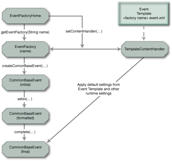
Figure 4 Common Base Event generation Note: This
illustration is for AC Toolkit and TPTP Java event generation; for the non-Java
implementation, EventFactoryHome does not
exist)
The structure shown in Figure 4 maps to the four steps involved in formatting an
event as shown in Table 1.
|
1.
Create the Common Base Event object
|
The event factory is used to create Common Base Event
objects.
Multiple event factories can exist, distinguished by name,
managed by the event factory home (see Best Practices). This allows separate
software sections (for example, components or subcomponents) to have unique
event factories.
|
|
2.
Assign event-specific values in the Common Base Event
|
The Common Base Event object provides a comprehensive set
of methods (the setxxx()
methods) that are used to supply and format the data associated with a Common
Base Event.
|
|
3.
Assign component default values in the Common Base
Event
|
The event factory refers to an event template that
contains the default values for all events created by the factory. These
values are copied into the Common Base Event object when the object is
completed. The template used by an event factory is determined by the name of
the event factory, allowing components using different factories to use
different default settings.
|
|
4.
Assign runtime values in the Common Base Event
|
These settings are inserted into the Common Base Event
object by the underlying event runtime (such as WebSphere Application Server)
when the object is completed. Runtime values can be environment information
(such as process IDs) or runtime-defined default settings for any required
properties. The underlying runtime documentation should provide information
explaining the default values and specify how to override defaults.
|
Table 1. Mapping
the event structure of Figure 4 to the steps for formatting an event
|
Best practices
|
|
�
Event factories are named using the standard
Java dot-delimited naming convention. Factory names should resolve to a
system, component, package or class name, depending on the granularity of the
configuration template.
�
The Common Base Event Programming Library
provides a reference implementation of the Event Factory Home that
configures events with default properties from a template XML file. The
template XML file contains an XML Common Base Event with various properties
set. The naming convention used for the template XML file is <Event Factory name>.event.xml.
|
More details about the Common Base Event Programming Library
for the AC Toolkit and in TPTP can be found in detailed documentation such as
javadoc available with [ACTK] and [TPTP].
JSR-47 is the best practice for a logging facility; however,
some environments provide their own logging infrastructures that might be
appropriate to use.
Note: At
this time, JSR-47 cannot be used to create Common Base Events that will be
produced and consumed through the Common Event Infrastructure implementation. Rather,
as described in Formatting
a Common Base Event using the TPTP Common Base Event Programming Model on page 19, the Autonomic Computing Toolkit and TPTP programming
library should be used in conjunction with CEI.
Two aspects of the programming model are addressed here:
�
A basic event capture interface that does
not explicitly expose all the details of Common Base Event objects. The event
capture runtime maps the values provided by the interface to the Common
Base Event properties. It then creates a Common Base Event, using these mapping
rules and any other values provided by the interface implementation. The event
capture runtime also augments the Common Base Event with any
environment-specific values or runtime-defined default settings.
�
An advanced event capture interface that
exposes the details of the Common Base Event object and allows the component
full control over the settings in the Common Base Event. The component formats
the Common Base Events with all component data and invokes the event capture
runtime, supplying the Common Base Event object. The event capture runtime
is responsible for supplying any environment-specific values or
runtime-defined default settings.
Note: This document does not
address a third aspect of the programming model, in which the component uses a basic
event capture interface and an event capture runtime that are not
based on the Common Base Event model. This model uses an adapter to transform
the event information captured by the runtime to Common Base Events.
Basic event capture interfaces capture Common Base
Events using an interface that does not expose all of the details of the Common
Base Event to the application programmer. The following description of the
implementation provided in WebSphere Application Server, Version 6.0
demonstrates how a basic event capture interface can be used to capture Common
Base Events, using JSR-47 as the basic event-capture interface. JSR-47, or java.util.logging, defines Java 1.4 interfaces
used to capture problem determination data, such as log and diagnostic events. JSR-47
provides a specific set of interfaces optimized for capturing problem
determination data easily and quickly.
Note: Most
basic event capture interfaces are specific to a specialized class of events. For
example, JSR-47 is used to capture problem determination events, such as log and
diagnostic events.
Figure 5 illustrates how applications can create Common Base
Events using the JSR-47 interfaces. JSR-47 uses the concept of loggers
to capture events (represented in JSR-47 by LogRecord objects), using methods supplied by
the Logger
class to format and capture the event information.

Figure
5 Basic
event capture: Creating problem determination Common Base Events with JSR-47
interfaces
The Java logging processing for log events using named loggers
proceeds as follows:
1.
Application code invokes a Logger with event-specific data.
2.
The Logger
creates a CommonBaseEvent
using the createCommonBaseEvent()
method of the EventFactory
associated with the Logger.
The logger determines the event factory to use by using the name of the logger
to locate the name of the event factory.
3.
The Logger
wraps the CommonBaseEvent
in a CommonBaseEventLogRecord
and adds event-specific data, using information supplied when the Logger was invoked.
4.
The Logger
calls CommonBaseEvent�s
complete()
method.
5.
CommonBaseEvent
invokes ContentHandler�s
completeEvent()
method.
6.
The ContentHandler
adds XML template data to CommonBaseEvent
(including component default event settings, such as the component name). The
template file to use is defined by the event factory, and typically has a default
of <factory name>.event.xml.
7.
The ContentHandler
adds runtime data to the CommonBaseEvent
(including, for example, the current thread identifier).
8.
The Logger
passes the completed CommonBaseEventLogRecord
to the JSR-47 handlers associated with the Logger.
9.
The handlers format the data and write to the output devices
associated with the handlers, such as log repositories.
More details about the WebSphere Application Server support of
Common Base Events and using JSR-47 to format and capture them can be found at http://publib.boulder.ibm.com/infocenter/ws60help/index.jsp?topic=/com.ibm.websphere.nd.doc/info/ae/ae/rtrb_cbejavaapi.html.
Advanced event capture interfaces are used to capture
Common Base Events directly, allowing the application to directly control the
contents of the generated Common Base Event. Advanced event capture still uses
a runtime-specific interface to capture the event, but this interface can use a
Common Base Event object as input. The advanced event capture illustration here
uses the JSR-47 implementation provided in WebSphere Application Server 6.0,
but also uses the extensions provided in WebSphere Application Server to supply
a Common Base Event object as an input to the interface. This provides a good
comparison with the basic event capture interface described on page 21.
Note: The
JSR-47 interface is still customized to capture problem determination events
and expects the Common Base Event objects supplied to the interface to contain
those types of events. More general event capture interfaces are available that
allow the capture of any type of event, as well as routing and formatting the
event based on policies and other configurable criteria.
Figure 6 shows how an application can use the Common Base
Event Programming Library to create and format an event, and then use an
extended JSR-47 interface to capture the event.
Figure 6 Advanced event capture: Creating and
formatting an event using JSR-47 for event capture
The steps for generating a Common Base Event are as follows:
1.
The application invokes the createCommonBaseEvent() method of EventFactory to
create a Common Base Event object.
2.
The application wraps the CommonBaseEvent in a CommonBaseEventLogRecord and adds
event-specific data using the methods provided by the CommonBaseEvent object.
Note: The need to wrap the
Common Base Event in a CommonBaseEventLogRecord
is specific to the JSR-47 interface, which expects a LogRecord object as input.
3.
The application adds event-specific data and calls CommonBaseEvent�s complete() method to
finalize the event.
4.
The Common Base Event invokes ContentHandler�s completeEvent()
method (the ContentHandler invoked is specified by the EventFactory).
5.
The ContentHandler
sets default data for the Common Base Event (including, for example, the
component name), by using the XML template data associated with the ContentHandler.
6.
The ContentHandler
sets runtime data for the Common Base Event (including, for example, the
current thread identifier).
7.
The application passes the finalized CommonBaseEventLogRecord
to the JSR-47 Logger
using the Logger.log
method.
8.
The Logger
passes the CommonBaseEventLogRecord
to JSR-47 Handlers associated with the Logger.
9.
The handlers format the data and write to the output devices
associated with the handlers, such as log repositories.
|
Best practice
|
|
The application can use any EventFactory to create a Common Base Event,
but it�s best to use the same EventFactory
and template files employed by the underlying event capture runtime�s basic
event capture interface. For example, in the JSR-47 implementation, use
the EventHandler
with the same name as the JSR-47 Logger, and use a template file that follows the <factory name>.event.xml
convention. In this way, the same default settings and behavior are used to
format Common Base Events, regardless of whether the application is using the
basic or advanced event capture interfaces (or both).
|
More details about the WebSphere Application Server support of
Common Base Events and capturing them using JSR-47 can be found at: http://publib.boulder.ibm.com/infocenter/ws60help/index.jsp?topic=/com.ibm.websphere.nd.doc/info/ae/ae/rtrb_cbeapi.html.
An event producer (sometimes called an event
source) is any application that reports Common Base Events. One recipient
of such events is the CEI Server. To send Common Base Event events to the CEI
Server, the event producer uses the CEI Emitter library. The CEI Emitter
supports both J2EE and J2SE applications and requires the WebSphere Application
Server client. The preceding sections described how to generate Common Base
Events. This section addresses how to send events using the CEI Emitter, for
those applications that use CEI, including characteristics of the CEI event
emitter that can influence the way in which events are processed by the CEI server.
For details about the CEI Programming Model, see the
publication [CEIDEV].
Note that the WebSphere Process Server 6.0 and WebSphere
Business Integration Foundation, Version 5.1.1 products include an interface
called Event Correlation Sphere that serves as an optional wrapper of
the CEI Event Emitter API. See the appropriate product publications [CEIRB] and
[WPSP] for additional information.
�
CEI
emitter configuration
An emitter is obtained from an emitter factory. The emitter
factory is configured through a CEI emitter factory profile, using WebSphere
Application Server configuration and administration panels. The CEI emitter
properties include:
�
J2EE transaction mode
- SAME - Event is
rolled back if the caller�s transaction is rolled back
- NEW - Event is not
rolled back if the caller�s transaction is rolled back
�
Synchronization mode
- Synchronous - the
sendEvent()
call does not return until the event is persisted and published
- Asynchronous - the sendEvent() call
returns immediately
�
Filter plug-in
- Default provided
by CEI
- Optional
user-written code that implements the isEventEnabled() interface
In addition to these properties, the emitter configuration
also defines the connection used by the CEI emitter to send events to the CEI
Server.
The emitterFactory
is accessed through the JNDI lookup. After the event producer has an emitterFactory, it
can use the getEmitter()
call to obtain an emitter, the EventFactory.createCommonBaseEvent()
method (or other mechanisms described in sections 1.4.9.1 and 1.4.9.2) to generate and populate Common Base Events and the Emitter.sendEvent() method to
submit the Common Base Event to the CEI server.
CEI
emitter SendEvent method
Example
1 shows how an event producer can send events using the
CEI emitter:
Context context = new InitialContext();
�EmitterFactory
emitterFx = (EmitterFactory)
� context.lookup("java:comp/websphere/emitter");
�Emitter
emitter = emitterFx.getEmitter();
�EventFactory
eventFactory = (EventFactory)
� context.lookup("java:comp/websphere/events/factory");
�CommonBaseEvent
event =
� eventFactory.createCommonBaseEvent("HighValueOrder");
�event.addExtendedDataElement("eventSource",
"TestApp");
�event.addExtendedDataElement("eventDomain",
"BUSINESS");
�event.addExtendedDataElement("eventPurpose",
"Info");
�event.addExtendedDataElement("customerNo",
"C03738927");
�event.addExtendedDataElement("orderNo",
"O56232-2003-May");
�event.addExtendedDataElement("orderValue",
"1394000");
�emitter.sendEvent(event);
Example 1 Sending
events using the CEI emitter
Common Base Events can be created and populated in various
ways, as described in preceding sections; Example
1 shows just one of these ways. In any case, the CEI event
emitter sendEvent()
method must receive a Common Base Event based on the AC Toolkit/TPTP
object.
|
Note:
|
|
CEI only supports a Java
representation of Common Base Events. TPTP has classes to serialize and
deserialize Common Base Events. CEI currently supports Common Base Event
version 1.0.1. Valid Common Base Events must include these attributes:
����������� - version=�1.0.1� (Do not
use the default value of 1.0)
����������� - creationTime
����������� - sourceComponentId
����������� - situation
GlobalInstanceId � the best practice is to allow the emitter to set this value. CEI
requires that this be set to a globally unique value.
|
The event producer can override
the default transaction mode and synchronization mode of the sendEvent() method when
necessary.
The sendEvent()
method performs the following steps:
1.
event.complete()
(application-supplied code)
2.
event.validate()
3.
Filters the plug-in (this may be application-supplied
code).
4.
Sends the event to the CEI server.
Completing
event contents automatically with the CEI emitter complete plug-in
Events can be created for many different situations. Each
situation could require unique code to populate the necessary properties of an
event. A content completion handler can be associated with an event
factory. You can use a completion handler to modify the events to be sent to
the CEI Server. The completion handler is called by the emitter before the
event is sent.
�
|
Note
|
|
Content completion handlers might be used to set attributes
common to all events. They also might be used to enforce policies, such as
setting the severity based on the time of day.
|
Filtering
events in the CEI emitter
Filtering should occur close to the source to reduce network
traffic and decrease the amount of log information. Filtering is a plug-in, so it
can be supplied by the application. A default filter plug-in is provided with
CEI. The plug-in implementation returns a Boolean value: either the event passes
filtering or it does not. A filter plug-in is associated with an emitter. When
an event is sent, the emitter calls the filter to determine whether or not the
event should be sent. A return value of true indicates that the event should be sent.
If the return value is false,
the event is discarded.
|
CEI emitter best practices
|
|
1.
If filtering is enabled in the emitter profile,
ensure that the XPath expression matches some events. Otherwise, no events are
sent to the CEI Server. No indication is returned to the event source when an
event is filtered. Therefore, ensure that testing procedures include sending a
variety of events, along with subscribing or querying to ensure that the
selected events are received by the CEI Server.
2.
Make sure that the Validate() and complete() methods are
not be called directly, because they are automatically invoked by the CEI
emitter library.
3.
Check that the Common Base Event version is set to 1.0.1.
4.
Make sure that the globalInstanceId is not set by the
application, because the emitter automatically generates a globalInstanceId that
is guaranteed to be globally unique.
5.
Decide with synchronization mode to use � synchronous compared to asynchronous:
����������� - SYNCHRONOUS � used when is known that an event is
persisted and distributed
������������������������������ before
the call returns to the source.
������������ - ASYNCHRONOUS � allows the application to continue
processing immediately
����������������������������� �after the sendEvent() call. If synchronous mode is
not required, an event
������������������������������ producer
should use the asynchronous mode to achieve better performance
������������������������������ results
under the same conditions.
6.
Decide which transaction mode to use � same compared with new:
����������� - SAME � The event is sent in the caller�s transaction.
This allows multiple events
������������������������������� to be
sent in a single transaction, so that if the caller�s transaction is rolled
back,
������������������������������� all the
events are also rolled back.
�����������
- NEW � The event is
sent in a new transaction and is processed regardless of
������������������������������ whether
or not the caller�s transaction is rolled back. If there is no need for
events
������������������������������ to be
processed within the same transaction, the event producer should use the
������������������������������ new mode to achieve
better performance results under the same conditions.
|
CEI provides additional facilities for managing and
receiving events, including:
�
Classifying the event using CEI event groups
(which control event routing and persistence)
�
Publishing the event to subscribing event
consumers (as event notifications) using JMS topics and queues. The CEI notification
helper is used to convert the JMS message into a Common Base Event.
�
Persisting the event in the CEI event
repository.
�
Querying and managing events in the CEI event repository,
including purging unused events.
For details on the CEI Programming Model, see [CEIDEV].
Event groups are an important configuration concept for CEI.
Event persistence and routing are two significant processes in the CEI Server.
All of these topics relate to the event life cycle and can affect how events
are consumed by applications that use CEI. Each of these topics is detailed in
the following sections.
1.4.9.4.1.1
Event groups
The event
group is an important concept in CEI that is part of the CEI programming
model. Event groups are used for subscriptions and queries. When subscribing to
events, the event consumer should specify the event groups it is interested in.
The event consumer receives only those events that match the event group
definitions specified in the subscription. Event groups also should be
specified for event queries (although there are other ways to query events that
do not require event groups). Event groups are defined through the WebSphere
Application Server (WCCM) administrative console. An event group is formed by
an XPath
expression, using any properties of the Common Base Event, plus an associated topic
name for publication. The event group contains:
�
The topic name for publishing the Common Base
Events that match this event group
�
The XPath expression that qualifies the event group
Some additional characteristics of event groups are:
�
A single event could belong to multiple event
groups
�
Multiple subscribers can receive the same event
if they share event groups
Event groups are defined by a regular expression event
selector.
|
Notes:
|
|
�
Event groups that are too broad (selected with
coarse granularity) could create unnecessary overlap among events. This can
result in duplicate data being published with separate events and can have a
negative impact on the overall application performance.
�
Overlapping event groups can result in
duplicated events being received when subscribing to multiple event groups.
�
Event groups that are too narrow (selected
with fine granularity) could create event groups that might not be used (that
is, might never match the event group selector) and could have a negative
impact on the overall application performance.
|
The CEI server receives Common Base Events and persists the
events in a database known as the CEI event repository. An administrator
can enable or disable persistence in the event server through a configuration
parameter. By default, event persistence is enabled. The CEI Server converts
the event from the internal format used by CEI to the CEI event repository schema
and uses the JDBC interface to connect to the database server configured for
CEI (which serves as the event repository). After being persisted, the Common
Base Events are sent to the routing process (described in �Event routing
(event publication)� on page 29) to be routed and published using the platform messaging
publication/subscription mechanism. The CEI server also provides an event repository
plug-in interface through which a product that embeds CEI can provide its own
event repository implementation to replace the CEI default event repository.
The default event repository can be queried using interfaces
described in [CEIDEV]. See �Event
querying� on page 30 for more information on event querying.
The CEI server determines which event groups match each
Common Base Event and then publishes the event using the platform messaging
publication and subscription mechanism. Event publication in CEI is based on
the classification of events according to the event groups that are specified
in the CEI server.
An event consumer is any
application that requires access to event information. The events can be
consumed asynchronously, through subscription to the publish/subscribe
mechanism supported by ESB and exploited by CEI server, or synchronously,
through interfaces that allow querying, updating and purging event information
in the CEI event repository through CEI access interfaces.
1.4.9.4.2.1 Event subscription
CEI uses JMS publish/subscribe
mechanisms to publish events to event consumers. Hence, CEI subscription is
achieved using standard JMS subscriptions. Event consumers must specify topics
in their subscriptions. In addition to the event group, event consumers also
can specify a filter selector that further restricts the set of events that
this event consumer receives.
|
Best practice
|
|
Event group qualification is run
in the CEI server. Event selector filtering is run in the CEI client. When
specifying event groups and event selectors, consider this difference that
can affect performance characteristics.
|
Event group subscriptions can be associated with
publish/subscribe topics or with queues:
�
Topics are used to send the same event to
multiple consumers
�
Queues are used to send events to a single
consumer
JMS can be configured with persistence to avoid event loss.
Use the CEI notificationHelper
to convert from JMS to Common Base Event.
�
Use the notificationHelperFactory to obtain a notificationHelper
�
The notification helper can filter events using an
XPath expression.
Example
2 shows an example of event subscription.
Context context = new InitialContext();
NotificationHelperFactory
helperFactory = (NotificationHelperFactory)
� context.lookup(�java:comp/env/cei/notification�);
NotificationHelper helper
= helperFactory.getNotificationHelper();
��
helper.setEventSelector(eventSelector);
��
String jmsSelector =
� helper.getJmsMessageSelector(�/CommonBaseEvent[@severity>50
and @extensionName=\�customer_order\�]�);
JmsPortProfile jpp = helper.getJmsTopic(�critical_events�,
��������� �context);
��
TopicConnectionFactory tcf =
(TopicConnectionFactory)
context.lookup(jpp.getConnectionFactoryJndiName());
TopicConnection tc =
tcf.createTopicConnection();
Topic t =
(Topic)context.lookup(jpp.getDestinationJndiName());
��
TopicSession ts =
tc.createTopicSession(false,
���������� Session.CLIENT_ACKNOWLEDGE);
TopicSubscriber subscriber =
ts.createSubscriber(t,
������������ jmsSelector,
������������ false);
subscriber.setMessageListener(this);
�
public void onMessage(Message msg) {
CommonBaseEvent event = helper.getCreatedEvent(msg);
�
}
Example 2. Event
subscription
Events can be queried in CEI using different mechanisms:
�
Query by globalInstanceId
�
Query event groups (optionally specifying an
event selector and the maximum number of events to return)
�
Query for existence
�
Retrieve associated events
These methods offer different performance characteristics.
Querying by globalInstanceId
typically provides the best performance results. Example 3 shows an example of an event query using an event
group.
InitialContext context = new
InitialContext();
�Object
eventAccessHomeObj = context.lookup("java:comp/env/cei/access");
�EventAccessHome
eventAccessHome = (EventAccessHome)
� PortableRemoteObject.narrow(eventAccessHomeObj,
�������� EventAccessHome.class);
�EventAccess eventAccess
= (EventAccess)eventAccessHome.create();
��
�List events =
eventAccess.queryEventsByEventGroup("critical_events",
���� �"/CommonBaseEvent[@severity>50 and
@extensionName=\"customer_order\"]",
���� �true, // ascending order
���� �5000); // max number of events
�Iterator iter
= events.iterator();
Example 3. Query using event groups
|
Best practice
|
|
To achieve adequate performance, event queries should be
defined such that the resulting set of events should return a relatively
small number of events, and events which are relatively small in size.
|
This section focuses on the
relationships among the Common Base Event, CEI and the WebSphere enterprise service
bus product (WESB).
�������������������������������������������������������������������������������������
�
The Common Base Event is the
standard message format for events related to business management, including
events related to IT systems as well as events related to business activity. By
integrating CEI, the WESB provides specialized support for these events.
|
Note:
|
|
The WESB provides support for mediation between software
running in the same or different organizational units, irrespective of
platform and programming model; because of this, it does not dictate nor
constrain the message format. WESB can provide specialized support for Common
Base Events through CEI integration, but Common Base Events are not the only
data format used for interactions among applications that are connected using
the WESB.
|
CEI can provide an event usage pattern for the WESB that
includes persistence, querying, updating of events, filtering and topic-based
distribution to event consumers. CEI is based on the platform messaging
available in WebSphere. This allows the CEI configuration to be integrated with
WESB configuration in the WebSphere Application Server administration console.
The purpose of this is to ensure that the tasks involved in administering CEI
are as simple and consistent as possible with other tasks related to WESB
configuration.
�����������
The current CEI programming model includes the interfaces (the
CEI emitter) for applications to report Common Base Events. The CEI emitter,
which is based on the TPTP (see [TPTP]) open source project, provides a set of
additional services such as complete plug-in structure, filtering support and
monitoring using local log plug-ins. The programming model also includes
support for consumers: the event group concept allows a consumer to subscribe
to defined topics rather than subscribing to specific messages defined by the
event sources.
To illustrate the use of Common Base
Events, this Best Practices document presents the structure of a Common
Base Event and describes conventions and best practices for generating and
interpreting these events. This document focuses on the general usage of a
Common Base Event. It also includes information about specific uses of Common
Base Events for problem determination and business processes.
A Common Base Event can contain several structural elements.
These are:
�
Common �header� information
�
Component identification
�
Situation information
�
Extended data
�
Context data
�
Associated events and association engine
�
Message data
Not all of these elements are required in every Common Base
Event. Each of these structural elements has its own embedded elements and attributes.
The logical structure of a
Common Base Event is illustrated in Figure
7; this figure is used in the sections that follow to
help locate, within the Common Base event structure, the elements that are
described.

Figure 7 Common Base Event structure
The remainder of this chapter describes how to generate a
correct Common Base Event, providing specific information, including examples, tips
and best practices, for the contents of each of the Common Base Event elements.
In the following sections, we use different versions of Figure 7
Common Base Event structure �to highlight
the element that is being described, using an oval.
At the core of every Common Base Event are several elements
that must always be present. The content of these elements could determine what
is placed in other parts of a Common Base Event. The set of required elements
for a Common Base Event is small, to allow for a wide variety of situations to
be represented in a compact manner. All other elements are optional, although
some optional elements are likely to be needed (required) in certain domains,
such as problem determination or business events. These are detailed further in
�The remainder of the Common
Base Event (optional, but important, elements).
Notes:
1.
This document is organized to present all of the core required
properties in a Common Base Event first: The
Common Base Event core (required elements) followed by the elements that describe all
optional (but in many cases important) properties elements. The audience
for this document is all users of Common Base Events, so the placement of properties
into the required and optional chapters reflects the general �usage. For those interested in specific
domains, such as problem determination or business events, see the individual best
practices boxes that relate to those topics, as well as the subsequent chapters
that describe scenarios for problem determination and business events.
2.
In the following sections, some properties of optional
elements are listed as required. This means that although the element
itself is optional, if that element is included, then the required properties
of that element must be present.
Table 2
demonstrates and compares the required and optional elements for problem
determination and business events, as compared to the base requirements for
Common Base Events.
The elements required for all
Common Base Events are:
�
creationTime
�
sourceComponentId
(reporterComponentId
also is required, unless it is the same as sourceComponentId)
� Situation
All other elements are optional, although some optional
elements are likely to be needed (required) in certain domains, as detailed in
section The remainder of
the Common Base Event (optional, but important, elements) on page 69. For example, Common Base Events used for problem
determination typically need some of the optional elements to be supplied so
that they can be used effectively for that purpose. Common Base Events for
business applications typically need to include the extensionName and extendedDataElement
properties described on page 73 and 84.
Next we describe how to specify and interpret the required core
elements.
The version property is a string used to
identify the version of the Common Base Event specification to which the event
conforms, so that the event can be recognized and managed appropriately by
event consumers. The version property is intended to facilitate
compatibility and migration as the Common Base Event specification evolves.
This property is OPTIONAL. If version is not
specified, it is assumed to be 1.0. However, because the current version of the
Common Base Event specification is 1.0.1, this property SHOULD be treated as if
it were REQUIRED, and its value should be set to �1.0.1�.
|
Best practice
|
|
Although in the schema, version is optional, the default value is
not useful, so always set the appropriate value for version (currently �1.0.1�).
|

Figure 8 creationTime property
This element specifies the time at which this Common Base
Event was created. Because Common Base Events are created in response to a
situation, this is not necessarily exactly the same time that the situation
occurred. It uses a type called dateTime as specified in XML Schema. An
example value for this property, indicating December 31, 2001 at 12:00, is �2001-12-31T12:00:00�.
Additional indicators can be present in a dateTime type,
including �Z�
to indicate the current time zone in UTC, century coding and so on. Fractional
seconds also are permitted, for example, �2001-12-31T12:00:00.543�,
indicating 543 milliseconds after noon. In this respect, the creationTime
element SHOULD be as precise (for example, milliseconds or microseconds) as the
underlying platform�s precision. See the dateTime XML
schema specification for additional details about this data type.
|
Best practices
|
|
�
Event producers: Use the time and date
information from the underlying platform, operating system or server for the
date and time value for the creationTime
element.
Include the time zone information
in creationTime.
�
Event consumers: Events can be received
from multiple resources that use different clocks (remote events could even
be received from resources in multiple time zones). Normalizing the creationTime
timestamp across multiple events can be useful when correlating the events.
If the time zone information is
not specified, assume that creationTime
is specified in UTC.
|

�Figure
9 reporterComponentId and
sourceComponentId properties
The sourceComponentId identifies the component
that was affected by the situation. sourceComponentId is
of type ComponentIdentification, described in �ComponentIdentification� on page 42.
The sourceComponentId property is REQUIRED and
after values are set, they must not be changed. The event producer must provide
the sourceComponentId.
The reporterComponentId identifies the
component that reported the situation on behalf of the affected component. reporterComponentId
is also of type ComponentIdentification, described in �ComponentIdentification� on page 42.
The reporterComponentId property is REQUIRED
only if the reporting component is not the same as the source component, and after
a value is set, it must not be changed. Otherwise (if the source and reporter
are the same component), this property MUST NOT be present.
2.3.4
�Source and reporter component identification guidelines and best
practices
The Common Base Event concept of a source component and a
reporter component is explained further in this section. The source
component in a Common Base Event identifies the component that is affected
by the situation described in the Common Base Event. The reporter component
in a Common Base Event identifies the component that is reporting the
event. Often, the source and reporter are the same; in these cases, the Common
Base Event contains only the source component. Examples of cases in which the
source and reporter components can differ include:
�
The Common Base Event is reported by monitoring
software as the result of a condition that affects a component that is being
monitored by the monitoring software (for example, when an IBM Tivoli
monitoring agent detects that a database server is no longer available).
�
The Common Base Event is reported by software on
behalf of a component that is unable to report events (for example, a hardware
device driver reports an event because a hardware component is affected by a
failure).
�
The Common Base Event is reported by software on
behalf of other software that it hosts (for example, an application server or
operating system reports events that affect applications that it hosts).
�
The Common Base Event is reported by a software
adapter on behalf of an application that cannot be modified or instrumented
directly (for example, a protocol adapter or proxy reports events for the
component that it provides adapter services for or acts as a proxy for).
|
Best practice
|
|
Use reporterComponent
to specify that an event is being reported on behalf of another component. In
the preceding examples, the reporterComponent
SHOULD indicate the monitoring agent, device driver, application server,
operating system, adapter, or proxy that reports the event on behalf of the
source component.
|
It is also instructive to
describe conditions in which identifying both a source and reporter is not
appropriate. The following best practices address this circumstance:
|
Best practices
|
|
�
Do not use the reporter component to chain
errors or exceptions.
Consider the case in which a
Common Base Event is reported by a component as a result of a situation in
another component. The correct usage is for both components to report events
describing the situation that they experienced. In each event, the reporting
component should identify itself as the source, describe the situation from
the point of view of that component, and, where possible, provide correlation
information so that the related events can be correlated by analysis systems.
For example, if an EJB could not complete the processing of a request because
the EJB could not retrieve some required data from a database server, then
the EJB should report an event identifying itself as the source component.
The database server should report a separate event identifying itself as the
source component.
�
Do not compensate for a component that
fails to report its own event.
Consider again the previous
example, but now assume that the database server is unable to report its own
event. The EJB should still report an event identifying itself as the source
component; it should not report an event on behalf of the
database server. Separate monitoring components might be able to report a
separate event on behalf of the database server, identifying the database
server as the source component and the monitoring component as the reporter
component.
�
Do not change component identification
information for events that are simply transferred or copied.
Consider the case in which a
Common Base Event is reported by a data transformation engine (such as the
IBM Generic Log Adapter for Autonomic Computing) that converts log or
diagnostic information produced by a particular component into the Common
Base Event format. The source and reporter information in the original log or
diagnostic event should not be altered by the data transformation engine
(that is, the data transformation engine should not insert any component
identification information about itself into the Common Base Event).
|

Figure 10 Component identification
The ComponentIdentification type specifies the
detailed information about the components that are identified by the sourceComponentId
and reporterComponentId elements as seen in �sourceComponentId
and reporterComponentId� on page 40. The intent of the ComponentIdentification
type is to clearly identify an instance of a component at runtime, and it
provides multiple ways of doing so.
The ComponentIdentification
type provides a collection of
properties that are required to uniquely identify a component. The same
structure is used to identify both reporter and source components.
A Common Base Event can contain various kinds of information
about a component in the sourceComponent and reporterComponent elements.
The best way to understand the usage of these properties is to understand the
concepts and models used by the Common Base Event. These models are used to
describe how a component is structured (type information) and how it is
deployed (instance information).
A business solution is made up of multiple components.
A component can be made up of several internal subcomponents. Consistent
application of these concepts is critical for effective management of a
business solution, because all parts of the solution must use the same concepts
and practices when creating events. The following definitions and examples SHOULD
be used when creating Common Base Events.
Business solution
A business solution is the
business logic and business data used to address a set of specific business
requirements. A business solution typically consists of several components of
multiple types (applications, middleware and so on), combined in a particular
manner by an enterprise, to provide the functions, processes and resources
needed to address those requirements. The primary creator and manager of a
business application is the enterprise, and each enterprise uses its own
business processes and business solutions. Examples of business solutions are a
payroll application, an inventory application for a manufacturer and a set of
IT service management processes that manage the IT infrastructure itself.
Components
Components are the assets
developed and acquired by an enterprise to create a business solution. One type
of component is an asset created by the enterprise, typically for usage within
a specific business solution. For example, the ACME Corporation might create a
set of EJBs to represent the business logic required by its payroll
application. Another type of component is an asset produced by a vendor and
acquired by an enterprise. Examples of these components are hardware products,
such as servers, and software products, such as application servers and
databases. Components are deployable assets, developed either by the enterprise
or a vendor, and managed by the enterprise.
Subcomponents
A specific component, depending on
its complexity, could consist of several subcomponents. For example, IBM
WebSphere Application Server consists of many subcomponents, such as the EJB container
and the servlet engine. Subcomponent information is typically used only by the
creator of the component to manage the component, and as such, subcomponents
typically are not separately deployable resources in the enterprise. The
enterprise might deploy a change or update to a subcomponent, but generally
only as part of an overall component update. For example, a software fix for
the EJB container of IBM WebSphere Application Server (subcomponent) is
packaged and deployed as a software update to the IBM WebSphere Application
Server (component). Replacement of the processor in an IBM server (subcomponent)
is deployed as a physical part, but only as a part of the originally deployed
IBM server (component).
In short, a business solution is created and managed by the
enterprise as a set of components. Components are assets and products developed
or acquired, and deployed, by an enterprise to create a business solution, and
are managed as individual entities by the enterprise. A subcomponent is a
discretely identifiable part of a component, typically not managed individually
(as components are). Subcomponents can often be updated (based on advice from
the vendor) when they malfunction. Examples of a subcomponent are a Java class
or a CPU in a server.
The Common Base Event uses the following concepts to
identify deployed instances of components:
Component name
The component name provides the
asset name of the component, for example, the product name, such as �IBM
WebSphere Application Server� or �IBM eServer� xSeries�.� This name is used to
classify the components in a system as well as to access knowledge about the
component that might be relevant to the situation that is reported.
Component location
The component location is used to
provide information about where a specific instance of a component has been
deployed or installed. This information helps relate the event to the overall
operation of the encompassing business solution, and also provides information
about how to target and direct any recovery actions. Examples of component
location include the TCP/IP address or host name of a server (which can
identify not only a specific hardware server but also software deployed on that
server) and the physical location of a server.
Installation image
The installation image
identification is used primarily for software, to provide additional
information about where a specific instance of software is installed. It is
typically used to provide information needed to distinguish among multiple
installed images of software within the same location, for example, when
multiple copies of IBM WebSphere Application Server are installed on the same
system. Its primary use is to provide information needed to update the software
image of a software component, such as applying a software fix to IBM WebSphere
Application Server or updating a deployed EJB.
Operational instance
The operational instance is used
to identify the running instance of a component, typically a software
component. It is typically used to distinguish among multiple operational
instances of a component at the same physical location or using the same
installed image, for example, when multiple instances of the same IBM WebSphere
Commerce Server are running on the same system. Its primary use is to provide
the information needed to target operational commands (such as Start, Stop or
Update Configuration) to the specific instance of a component that reports an
event.
In short, the deployment model for Common Base Events
supports multiple operational instances of a component that are created from
the same installed image, multiple images of a component that is installed
(deployed) at the same location, and a component that is installed (deployed)
in multiple locations.
Table
3 describes the elements in the ComponentIdentification
type that are used to represent the concepts described in the component
structure and deployment models.
|
Element name
|
Model concept
|
Description
|
|
location,
locationType
|
Component location
|
Identifies the location of the component
|
|
application
|
Business solution (application) name
|
Identifies the business solution or process that the
component is part of or provides services for
|
|
component,
componentType
|
Component name
|
Identifies the asset name of the component, as well as the
type of component
|
|
subcomponent
|
Subcomponent name
|
Identifies a specific part (subcomponent) of a component,
such as a software module or hardware part
|
|
instanceId
|
Operational instance
|
Identifies the operational instance of a component, that
is, the actual running instance of the component
|
|
processed,
threadId
|
Operational instance
|
Identifies the operational instance of a component within
the context of a software hosting environment, that is, the hosting
environment�s (for example, operating system�s) process and thread that were
running when the event was reported
|
|
executionEnvironment
|
Operational instance,
component location
|
Provides additional information about the operational
instance of a component or its location by identifying the name of the
environment that hosts the operational instance of the component (for
example, the operating system name that hosts a software application, the
application server name that hosts a J2EE application or the hardware server
type that hosts a hardware part)
|
Table 3. Component
identification properties and their associated representations
|
Note
|
|
Table
3 does not show any information that identifies the
installation image of the component. This version of the Common Base Event
does not provide a specific property to identify installation information. The
ExtendedDataElement
property could be used to provide information that identifies the
installation image of the component reporting the event (perhaps with an extensionName of InstallId of type string).
|
The following sections provide additional details about the
component identification elements. Appendix A.1 offers a model to use for specifying componentIdentification
values.
The location property specifies the physical
address that corresponds to the location of
a component. This address could be one of many different types (for example, IP
address, host name or other), so the locationType property (described next) indicates the type of
location address.
Examples of locations
include:
�
host name (mymachine.ibm.com)
�
IPv4 address (1.87.123.4)
�
Medium Access Control (MAC) address (09:01:00:03:71:CE)
This property is a REQUIRED part of the sourceComponent
and reporterComponent elements.
|
Best practice
|
|
The recommended method for identifying the location of a
component is a fully qualified host name (for example, �mymachine.ibm.com�).
|
This property specifies the format and meaning of the value
in the location property. The location types defined in the Common
Base Event specification [CBE101] are:
�
IPV4 �������������� - Internet Protocol version 4 (for example, 1.87.123.4)
�
IPV6��������������� - Internet Protocol version 6 (for example,
����������������������� ��A6C7:43C6:7901:12DE:7171:80FC:1234:CDEF)
�
NWA�������������� - see the following CIM note
�
ISDN������������� - see the following CIM note
�
ICD���������������� - see the following CIM note
�
OID-OSI ������� - see the following CIM note
�
Dial���������������� - see the following CIM note
�
HWA�������������� - see the following CIM note
�
HID���������������� - see the following CIM note
�
X25���������������� - see the following CIM note
�
DCC��������������� - see the following CIM note
�
SNA��������������� - see the following CIM note
�
IPX����������������� - see the following CIM note
�
E.164�������������� - see the following CIM note
�
Hostname ����� -
Name of the hosting system (for example, �mymachine�)
�
FQHostname
- Fully qualified name of the hosting system (for example,
����������������������� ���mymachine.ibm.com�
�
Devicename � - Name of
a device (for example, �mystoragedevice�)
�
Unknown������� - Use when the location
value does not conform to one of the well-known�
types
This property is a REQUIRED part of the sourceComponent
and reporterComponent elements.
|
CIM note
|
|
The properties just noted that refer to this note are
defined in the Common Information Model (CIM) of the Distributed Management
Task Force (DMTF). See http://www.dmtf.org/standards/cim.
These values can be useful when CIM is used in a management solution and CIM
information needs to be encoded in a Common Base Event.
|
|
Best practice
|
|
The recommended method for identifying the location
of a component is a fully qualified hostname (for example, �mymachine.ibm.com�).
The corresponding locationType
property is �FQHostname�.
|
The application property specifies the
human-readable �common� name of the associated business solution (for example, �Stock Quota & Sales�).
The application version information optionally MAY be appended to the end of
the name, separated by a �#�
character (for example, �Stock
Quota & Sales#3.2�). It is RECOMMENDED that the vendor name be
prepended to the application name (for example, �IBM Stock Quota & Sales#3.2�).
This property is an OPTIONAL part of the sourceComponent
and reporterComponent elements.
|
Best practice
|
|
Although this property expresses human-readable
information, it also can be used for automated event correlation, so use
consistent naming for applications, as described in the preceding
recommendation.
|
|
PD usage note
|
|
This property is an optional value within the Common Base
Event specification, but it SHOULD be provided within problem determination
events whenever it is known.
|
The component property identifies the manageable
resource associated with the event. A component is a hardware or software
component that can be separately obtained or developed, deployed, managed and
serviced, as described in �Component identification concepts and usage� on page 43),. The component version
information optionally may be
appended to the end of the name, separated by a �#�
character. It is recommended that
the vendor name be prepended to the component name (see the examples for
application on page 47).
Examples of typical
component names are (see also the component identification model in Appendix A.1 �How
to assign ComponentType values�):
�
�IBM
eServer xSeries model x330�
�
�IBM
WebSphere Application Server#5.1� (5.1 is the version number)
�
�Microsoft
Windows 2000�
�
The name of an internally developed software
application or EJB
�
The name of a separately addressable collection
of Java classes (�com.mycompany.mypackage�)
The type of the
information specified in component
(product, system, and so on) is described in the componentIdType property, described later.
This property is a REQUIRED
part of the sourceComponent
and
reporterComponent elements.
|
Best practice
|
|
For
the component value,
use the name of the product (software name, hardware server name). Include
the name of the vendor that supplied the product and any applicable version
information (for example, �IBM
WebSphere Application Server #6.1�). Whenever possible, use the same
value used to register the product in the system�s installation registry
(such as the Autonomic Computing Solution Installation registry).
|
The componentIdType
property specifies the format and meaning of the component
property (described earlier) that is identified in this sourceComponent
or reporterComponent element � that
is, the type of component that is identified.
The Common Base Event specification (CBE101)
defines these component types:
�
ProductName: ��������� Indicates that component
represents a specific product, for example,
����������������������������������� �IBM DB2 Universal Database�
�
�
DeviceName:������������ Indicates that component
represents a device, for example,
����������������������������������� �IBM Remote Supervisor
Adapter�
�
SystemName: ����������� Indicates that component
represents a system, for example, �Server Cluster�
�
ServiceName:���������� Indicates that component
represents a service, for example,
����������������������������������� �Stock Quote Service�
�
Process:������������������� Indicates
that component represents a business or
service management
����������������������������������������� process,
for example, �Stock Quota and Sales�
�
Application:���������� Indicates
that component represents an application
�
Unknown: ������������������ Indicates
that component is not one of these
types
This property is a REQUIRED part of the sourceComponent
and reporterComponent elements.
|
PD usage note
|
|
The
componentIdType property is required by the base Common Base
Event specification, but provides minimal additional value beyond that of
other component identification properties. For problem determination events,
the use of the application value is DISCOURAGED.
The componentIdType property
identifies the type of component; the application is identified by the application
property.
|
The componentType property identifies
the type of component that is identified by the component and componentIdType properties.
The componentType is a well-defined
name that is used to characterize all instances of a given kind of
component. For example, if the identified component is the IBM WebSphere
Application Server, the componentIdType property value SHOULD specify �ProductName� and the componentType property should specify that the component is a
J2EE Server.
This property is a REQUIRED part of the sourceComponent
and reporterComponent elements.
|
Best
Practice
|
|
A systematic way to specify component types
is required, to prevent name collisions and accidental misinformation.
Appendix A.1 �How to assign ComponentType values� describes a recommended methodology. It does
not provide a complete enumeration of all possible component types, but it
does describe how to derive other component types and offers examples for
some environments.
|
The subcomponent property identifies
the specific part of a component that is associated with the event, such as the
name of the specific subsystem within a component that reported an event. The
subcomponent name is typically not a manageable asset, but provides internal
diagnostic information for diagnosing internal defects within a component, as
described in �Component
identification concepts and usage� on page 43. Examples of typical subcomponents and their names
are:
�
Intel� Pentium� processor within a
server system (�Intel Pentium IV Processor�)
�
The EJB container within a Web application
server (�EJB container�)
�
The task manager within an operating system (�Linux Kernel Task Manager�)
�
The name of a Java class and method (�com.mycompany.myclass� �com.mycompany.myclass.methodname()�)
The format of the
subcomponent name is determined by the component. A component that cannot be
readily decomposed into subcomponents should supply the value �none�.
This property is a REQUIRED
part of the sourceComponent
and
reporterComponent elements.
|
Best practices
|
|
�
Use the convention described earlier for
naming a Java class or the combination of a Java class and method when
identifying Java code modules, for example, �com.mycompany.myclass�
or �com.mycompany.myclass.methodname()�.
More specifically, when including a method name, make sure to include the
parentheses �()�.
�
Use the same value that is used to register
the subcomponent (if applicable) in the system�s installation registry (such
as the IBM Autonomic Computing Solution Installation registry) for the
subcomponents that make up a component.
|
The executionEnvironment property specifies the hosting environment
for the component that is specified in the component property. It identifies the immediate environment
within which the component is operating. Some examples are:
�
The operating system name that hosts a software
application, for example, �RedHat Linux�
�
The operating system or JVM name that hosts a
Java 2 Platform, Standard Edition (J2SE) application
�
The Web server name that hosts a servlet
�
The portal server name that hosts a portlet
�
The application server name that hosts an EJB,
for example, �IBM WebSphere Application
Server#5.1�
Version information MAY
be appended to the end of the name, separated by a �#� character.
This property is an OPTIONAL
part of the sourceComponent
and
reporterComponent elements.
|
Best practice
|
|
The value placed
in the executionEnvironment property should
match the value that the hosting environment would use to identify itself
when the hosting environment reports events (that is, the value the hosting
environment uses for its own component name when
it reports events).
|
The instanceId property specifies the operational instance of the
component (that is, which operational instance of an installed software image) that
reports the event. The format of the value is defined by the component, but it
must be a value that can be used by an analysis system (either human or
programmatic) to identify the specific running instance of the identified
component. Examples include:
�
cell.node.server name for the IBM
WebSphere Application Server
�
deployed EAR file name for an EJB
�
serial number for a hardware processor
This property is an OPTIONAL
part of the sourceComponent
and
reporterComponent elements, but it should
be provided within problem determination events whenever it is known.
|
Best practice
|
|
The instanceID
property should be provided
when a software component is identified. This value should also be provided for hardware components if it is
known, although not all hardware components support the concept of
operational instances.
|
|
PD usage
note
|
|
This property is
optional in the Common Base Event specification, but it SHOULD be provided within
problem determination events whenever it is known.
|
The processId specifies the process identifier
of the �running� process within the component that reports the event (that is,
the identifier of the running process when the situation occurred), for those
hosting environments that include process identifiers. The format of processId should
match the format of the execution environment (such as an operating system). The
threadId
property (described next) can be used in conjunction with processId
to further delineate the instance of the component that generated the event.
This property is an OPTIONAL part of the sourceComponent
and reporterComponent elements, but it should be provided within problem determination events
whenever it is known.
|
Best practices
|
|
�
The processID property should
be provided for software-generated events (unless the software execution
environment does not support the concept of separate processes, or the
process identifier is not known). This property is typically not applicable
for events reported by hardware.
�
If used, the value of the processId property is
obtained from the hosting environment or platform.
|
|
PD usage note
|
|
This property is optional in the Common Base Event
specification, but it should be
provided within problem determination events whenever it is known.
|
The threadId specifies the thread
identifier of the �running� thread within the component that reports the event
(that is, the identifier of the running thread when the situation occurred), for
those hosting environments that include thread identifiers. The format of threadId should match
the format of the execution environment (such as an operating system). The processId
property (just described) can be used in conjunction with threadId
to further delineate the instance of the component that generated the event.
This property is an OPTIONAL part of the sourceComponent
and reporterComponent elements, but it should be provided within problem determination events
whenever it is known.
|
Best practices
|
|
�
The threadID property should
be provided for software-generated events (unless the software execution
environment does not support the concept of threads, or the thread identifier
is not known). This property is typically not applicable for events reported by
hardware.
�
If used, the value of the threadId property is
obtained from the hosting environment or platform.
|
|
PD usage note
|
|
This property is optional in the Common Base Event
specification, but it should be
provided within problem determination events whenever it is known.
|

Figure 11 Situation
The situation
element is one of the most important parts of a Common Base Event. This element
describes the situation that was detected, providing important information that
autonomic managers can use to perform self-configuring, self-healing,
self-optimizing and self-protecting functions.
The situation information is used to classify the condition
reported by an event. The Common Base Event specification (CBE101) provides
information about the set of situations defined for the Common Base Event (see
the description of the categoryName property on page 53). Each situation category has an associated set of
values that further describe the situation (see the description of the SituationType element on page 54).
|
Best practice
|
|
Whenever
possible, use the situation categorizations and qualifiers described in the
base Common Base Event specification. Avoid using your own situation
definitions.
|
|
PD usage notes
|
|
�
Not all log and diagnostic events can be
classified using the situation definitions supplied in the base Common Base
Event specification. You can use the �OtherSituation� category to provide your
own situation information, but the recommended
course of action for problem determination events is to use the most
appropriate SituationCategory
value whenever possible. In cases where none of the SituationCategory values apply, use the �ReportSituation� category, with reportCategory=�Log� (for log events) or reportCategory=�Trace� (for diagnostic events);
however, carefully scrutinize the event and situation categories to attempt
to find a more meaningful situation category that applies.
�
Warning events can be ambiguous. A warning
event (that is, an event with severity=�30�)
typically indicates a recoverable failure, but the situation values might
otherwise be interpreted as unrecoverable failures (for example, ConnectSituation, successDisposition=�UNSUCCESSFUL�). The
appropriate situation category should always be used, with the severity
setting indicating the severity of the situation; that is, whether or not the
component recovered from the failure.
|
|
Business events usage note
|
|
In
Common Base Event version 1.0.1, the predefined situation categories have
limited applicability to business events. The best practice is to use �ReportSituation� with reportCategory set to �PERFORMANCE� or �LOG� when communicating the
value of a metric, and the �OtherSituation�
category in other cases.
|
This property categorizes the
situation reported by the event. The Common Base Event specification [CBE101]
defines these situation categories:
�
StartSituation
�
StopSituation
�
ConnectSituation
�
ConfigureSituation
�
RequestSituation
�
FeatureSituation
�
DependencySituation
�
AvailableSituation
�
CreateSituation
�
DestroySituation
�
ReportSituation
�
OtherSituation
Each situation category has a
set of associated properties, defined in the SituationType element
described next.
This
is a REQUIRED property.
The SituationType element provides the
additional data associated with each situation category (as indicated by the categoryName property just
described). SituationType is an abstract element that is used to specify all of the supported
situation types, with the specific element to use having the same name as the
situation category (that is, the value specified by the categoryName property).
The situation category, to be of value, must be applied
consistently. Hence, the description of each situation type element not only
describes the additional values associated with a situation category, but also
describes details associated with the best practices for each situation
category.
The SituationType
element is a REQUIRED property, and the specific SituationType element used must be the one
associated with the situation category specified by the categoryName property.
The following sections describe the format of each specific
situation type element. All elements contain the reasoningScope property, so it is described
separately.
This
property specifies the scope of the situation. The reasoningScope
property defines whether the impact of this situation is internal or external. The reasoningScope values defined in the Common Base Event specification
(CBE101) are:
�
INTERNAL � the impact of this situation is contained within the
component that is
����������������������� reporting
the situation
�
EXTERNAL � the impact of this situation can extend outside of the
component that is
����������������������� reporting
the situation
This
is a REQUIRED property for all situation types, and it is a common property of all
the specific SituationType elements described in the following sections.
|
PD usage note
|
|
The recommended value for reasoningScope value is �EXTERNAL� for all log and
diagnostic events.
|
The StartSituation
element is the specific SituationType
element used to describe a start situation (that is, categoryName=�StartSituation�).
|
Best practices
|
|
�
Events
that indicate that a component has begun the startup process, that it has
finished the startup process or that it has aborted the startup process all
fall into this category. Associated log messages typically include words such
as starting, started, initializing and initialized,
for example:
DIA3206I The TCP/IP
protocol support was started successfully.
DIA3000I "%1S"
protocol support was successfully started.
DIA3001E "%1S"
protocol support was not successfully started.
WSVR0037I: Starting EJB
jar: {0}
�
A single Common Base Event can represent an
entire start situation. For example, a start situation that specifies SituationQualifier=�START COMPLETED� and successDisposition=�SUCCESSFUL� indicates that the entire startup
process has been successfully completed.
�
The startup process could be specified with
finer granularity, using multiple Common Base events, using several start
situations such as:
SituationQualifier=�START INITIATED�,
successDisposition=�UNSUCCESSFUL�
SituationQualifier=�RESTART INITIATED�,
successDisposition=�SUCCESSFUL�
SituationQualifier=�START COMPLETED�,
successDisposition=�SUCCESSFUL�
This sequence indicates that the first
attempt at starting was unsuccessful, so a restart was attempted, which was
successful, followed by an indication that startup process has been successfully
completed.
|
The StartSituation element includes the
following properties.
This property specifies whether
or not the startup process described by this event was successful. The successDisposition values defined in the Common Base Event specification
(CBE101) are:
�
SUCCESSFUL
�
UNSUCESSFUL
This is a REQUIRED property within
the StartSituation element.
This
property specifies additional information to further describe the start
situation. The situationQualifier
values defined in the Common Base Event
specification (CBE101) are:
�
START INITIATED
�
RESTART INITIATED
�
START COMPLETED
These values enable a �start�
process to be described with finer granularity, as shown in the best practice
on page 55.
This is a REQUIRED property within
the StartSituation element.
This is a property common to all SituationType elements (refer to �reasoningScope� on page 54 for a description of this property). This is a REQUIRED property within the StartSituation element.
The StopSituation
element is the specific SituationType
element used to describe a stop situation (that is, categoryName=�StopSituation�).
|
Best practices
|
|
�
Events
that indicate that a component has begun to stop, that it has stopped or that
the stopping process has failed all fall into this category. Associated log messages
typically include words such as stop, stopping, stopped,
completed and exiting, for example:
WSVR0220I: Application stopped: {0}
WSVR0102E: An error occurred stopping, {0}
MSGS0657I: Stopping the MQJD JMS Provider
In a manner similar to
the start situation, a single Common Base Event can represent an entire stop
situation or a stop situation also could be specified with finer granularity,
using multiple Common Base events. See the examples in the best practice on page 55 for
example patterns that are similar to those that could be used for stop
situations.
|
The StopSituation element includes the
following properties.
This property specifies whether
or not the stop process described by this event was successful. The successDisposition values defined in the Common Base Event specification
(CBE101) are:
�
SUCCESSFUL
�
UNSUCESSFUL
This is a REQUIRED property within
the StopSituation element.
This property specifies
additional information to further describe the stop situation. The situationQualifier values defined in the Common Base Event
specification (CBE101) are:
�
STOP INITIATED
�
ABORT INITIATED
�
PAUSE INITIATED
�
STOP COMPLETED
These values enable
a �stop� process to be described with finer granularity, as shown in the StopSituation best practice below �StopSituation� on page 57.
This is a REQUIRED property within the StopSituation element.
This
is a property common to all SituationType
elements (refer to �reasoningScope� on page 54 for a description of this property). This is a REQUIRED property within the StopSituation element.
The ConnectSituation
element is the specific SituationType
element used to describe aspects about a connection to another component (that is, categoryName=�ConnectSituation�).
|
Best practices
|
|
�
Messages
that indicate that a connection failed, that a connection was created or that
a connection has ended all fall into this category. Existing log messages
typically include words such as connection reset, connection failed
and failed to get a connection, for example:
DBMN0015W:
Failure while creating connection {0}
DBMN0033W:
connection connection close failure {0}
DBMN0023W: Failed to close a connection {0}
�
In a
manner similar to other situations, a single Common Base Event can represent
an entire connection process or a connection process also could be specified
with finer granularity, using multiple Common Base events. See the examples
in the start situation best practice (see StartSituation on
page 55), for example, patterns that are similar to those
that could be used for connect situations
|
The ConnectSituation element includes the
following properties:
This property specifies whether
or not the connection process described by this event was successful. The successDisposition values defined in the Common Base Event
specification (CBE101) are:
�
SUCCESSFUL
�
UNSUCESSFUL
This is a REQUIRED property within
the ConnectSituation element.
This property specifies
additional information to further describe the connection process. The situationDisposition values defined in the Common Base Event
specification (CBE101) are:
�
INUSE����� - a connection is being used
�
FREED����� - a previously established connection is no longer in use
�
CLOSED���� - a previously established
connection has ended
�
AVAILABLE� - a connection capability exists
This is a REQUIRED property
within the ConnectSituation element.
This
is a property common to all SituationType
elements (refer to �reasoningScope� on page 54 for a description of this property). This is a REQUIRED property within the ConnectSituation element.
The ConfigureSituation
element is the specific SituationType
element used to identify information about a component�s configuration data and
to indicate changes to that data (that is, categoryName=�ConfigureSituation�).
|
Best practices
|
|
�
Any
changes made to a component�s configuration data
should be represented with this situation category. Additionally, messages
that describe the current configuration state fall into this category.
Because many different names and types exist for configuration properties,
some analysis is required to determine if existing messages or events fall
into this category. Existing log messages might include words such as port
number, name, address, directory, path or numerous other configuration
properties. Existing messages might also contain words such as configure,
configured, configuration or set to (as in a property has been set
to some value), for example:
ADFS0134I: File
transfer is configured with host="9.27.11.13", port="9090",
securityEnabled="false"
�
However,
not all state changes involve configuration data, so not all seemingly
similar messages are configure
situations. Consider, for example, metric properties, which are distinct from
configuration properties. Many metric properties should be reported with a
report situation rather than with a configure situation.
�
Configure
situations could be reported in conjunction with other situations; for
example, a resource might report its current configuration state along with a
start situation. Configure situations also should be reported when
configuration data changes; for example, as a result of an operation that
alters a resource�s
configuration data.
|
The ConfigureSituation includes
the following properties:
This
property specifies whether or not the configuration situation (configuration
data or update) described by this event was successful.
The successDisposition values defined
in the Common Base Event specification (CBE101) are:
�
SUCCESSFUL
�
UNSUCESSFUL
This is a REQUIRED property within the ConfigureSituation element.
This
is a property common to all SituationType
elements (refer to �SituationType� on page 54 for a description of this property). This is a REQUIRED property within the ConfigureSituation element.
The RequestSituation element is the specific SituationType element used to represent the
processing of a request by a component (that is, categoryName=�RequestSituation�).
|
Best practices
|
|
�
Request situations typically relate to complex
management tasks or transactions that a component undertakes on behalf of a
requester, rather than the detailed processing associated with carrying out
the transaction. Messages that indicate that a request was made to perform a
transaction or operation or that such a request has completed fall into this
category. Existing log messages typically include words such as configuration
synchronization
(or some other transaction name) started or backup
procedure (or some other transaction name) complete, for
example:
ADMS0003I: Configuration synchronization completed
�
Request situations typically are a discrete
set of events with well-defined expectations. That is, a typical process
might involve a �REQUEST INITIATED�
(successfully or unsuccessfully) event, followed some time later by a �REQUEST COMPLETED�
(successfully or unsuccessfully) event.
|
The RequestSituation element includes the following properties.
This property specifies whether or
not the request situation described by this event was successful. The successDisposition values defined in the Common Base Event specification
(CBE101) are:
�
SUCCESSFUL
�
UNSUCCESSFUL
This is a REQUIRED property within
the RequestSituation element.
This property specifies
additional information to further describe the request situation. The situationQualifier values defined in the Common Base Event
specification (CBE101) are:
�
REQUEST INITIATED
�
REQUEST COMPLETED
This is a REQUIRED property
within the RequestSituation element.
This
is a property common to all SituationType
elements (see �reasoningScope� on page 54 for a description of this property). This is a REQUIRED property within the RequestSituation element.
The FeatureSituation
element is the specific SituationType
property (or abstract element) used to announce that a feature of a component is now
ready (or not) to service requests
(that is, categoryName=�FeatureSituation�).
|
Best practices
|
|
�
Situations that indicate that features or
services have become available or unavailable fall into this category. Related
log messages typically include words such as available, unavailable, ready,
installed and listening, for example:
SRVE0171I: Transport HTTPS is
listening on port 9443
MSGS0601I: WebSphere Embedded
Messaging has not been installed
IPDS05706: Printer collator
installed and available
�
The feature situation applies to the
operations and operational state of individual features of a component. The
operations and operational state of the component itself should be reported
using the AvailableSituation element described
in �AvailableSituation� on page 63.
�
See also the DependencySituation
element describe in �DependencySituation� on page 62, which is used to report situations that
might have similar keywords in existing messages. Feature situations are used
to communicate the capabilities of a component, whereas a dependency
situation is used to communicate the existence of a dependency relationship
between the component and some other resource. A component might use a FeatureSituation element to indicate that one of its
own features has become available or unavailable; whereas a component should
report the availability or unavailability of a feature that it depends on
using a dependency situation.
�
To summarize, Feature, Dependency and
Available situations are related yet distinct. To determine when to use one
of these situations, use the following guidelines:
����������������� - Feature: communicates the
status of a component�s own features (capabilities)
����������������� - Available: communicates
the status of a component itself
����������������� - Dependency: communicates
the existence or status of a component dependency (that is,
������������������� �the reliance on a feature or capability of
another component)
|
The FeatureSituation element includes
the following properties:
This
property specifies the availability disposition of a component feature associated
with this event. The featureDisposition values defined in the Common Base Event
specification (CBE101) are:
�
AVAILABLE
�
NOT AVAILABLE
This is a REQUIRED property within the FeatureSituation element.
This is
a property common to all SituationType elements (see �reasoningScope� on page 54 for a description of this property). This is a REQUIRED property within the FeatureSituation element.
The DependencySituation
element is the specific SituationType
property used to describe a dependency relationship between two components (that
is, categoryName=
�DependencySituation�).
This can include
situations in which a component indicates that it cannot find some other
component or capability that it depends upon (for example, the component cannot
connect to a required database).
|
Best practices
|
|
�
This category includes messages that indicate
that some dependency was met or not met. Such messages could take the form of
indications that a required component, file, resource, capability or feature
is (or is not) available or was found (or not found) or the version of a
component matches (or does not match) what was expected. Existing log messages
typically include words such as dependency, find, found, required, no such
or mismatch, for example:
WSVR0017E: Error encountered
binding the J2EE resource, Pet Store JMS Queue Connection Factory, as
jms/queue/QueueConnectionFactory from resources.xml no resource binder found
�
Dependency situations are distinguished from
available and feature situations by the existence of a dependency
relationship between the component and some other resource. A component might
use a feature situation to indicate that one of its own features has become
available or unavailable; whereas a component should report the availability
or unavailability of a feature that it depends on using a dependency
situation. See also the AvailableSituation
element described on page 63, which is used to report the operational state of
the component itself.
�
To summarize, Feature, Dependency and
Available situations are related yet distinct. To determine when to use one
of these situations, use the following guidelines:
����������������� - Feature: communicates the
status of a component�s own features (capabilities)
����������������� - Available: communicates
the status of a component itself
����������������� - Dependency: communicates
the existence or status of a component dependency (that is,
������������������� �the reliance on a feature or capability of
another component)
|
The DependencySituation element
includes the following properties.
This
property specifies the availability status of the dependency item associated
with the event. The dependencyDisposition values defined in the Common Base Event
specification (CBE101) are:
�
MET
�
NOT MET
This is a REQUIRED property within the DependencySituation element.
This
is a property common to all SituationType
elements (see section �reasoningScope� on page 54 for a description of this property). This is a REQUIRED property within the DependencySituation element.
The AvailableSituation element is the specific SituationType used to describe a component�s
operational state and availability (that is, categoryName=�AvailableSituation�).
|
Best practices
|
|
�
This situation provides a context for
operations that can be performed on the component by establishing whether or
not a product is installed, operational and ready to process functional
requests or operational and ready (or not ready) to process management
requests. Existing log messages typically include words such as available,
unavailable, ready, online and offline, for example:
ADMC0013I: SOAP
connector available at port 8880
ADMC0026I: RMI Connector available at port 2809
�
An available situation might be generated when
a component�s availability state changes or it could be generated as a result
of some other action. For example, a component might generate an available
situation that indicates NONSTARTABLE
as a result of a management request to start the component.
�
The available situation applies to the
component operations and operational state. The operational state of
individual features of a component should be reported using the FeatureSituation element described
on page 61. See also the DependencySituation element described on 62, which is used to report situations that might have
similar key words in existing messages.
�
To summarize, Feature, Dependency and
Available situations are related yet distinct. To determine when to use one
of these situations, use the following guidelines:
����������������� - Feature:
communicates the status of a component�s own features (capabilities)
����������������� - Available:
communicates the status of a component itself
����������������� - Dependency:
communicates the existence or status of a component dependency (that is,
������������������� �the reliance on a feature or capability of
another component)
|
The AvailableSituation
element includes the following properties.
This property specifies the
operational state (that is, its ability to be started or not) of the component associated
with the event. The operationalDisposition
values defined in the Common Base Event
specification (CBE101) are:
�
STARTABLE
�
NONSTARTABLE
This is a REQUIRED property within
the AvailableSituation element.
This
property specifies the availability disposition of the component associated
with the event. The availabilityDisposition
values defined in the Common Base Event
specification (CBE101) are:
�
AVAILABLE
�
NOT AVAILABLE
����������������������������������������������������������
This is a REQUIRED property within
the AvailableSituation element.
This property specifies the
processing disposition of a component operation associated with the event. The processingDisposition values defined in the Common Base Event
specification (CBE101) are:
�
FUNCTION_PROCESS���� - indicates
that a functional operation was processed
�
FUNCTION_BLOCK� - indicates that a functional
operation was blocked (not processed)
�
MGMTTASK_PROCESS���� - indicates
that a management operation was processed
�
MGMTTASK_BLOCKED���� - indicates
that a management operation was blocked (not processed)
This is a REQUIRED property within
the AvailableSituation element.
This is a property common to all SituationType elements (see �reasoningScope� on page 54 for a description of this property). This is a REQUIRED property within the AvailableSituation element.
The CreateSituation element is the specific SituationType used to describe a component�s
attempt to create some entity, such as a file, report or application EAR file. This
element is used when categoryName=�CreateSituation�.
|
Best Practice
|
|
Messages that indicate that a document, file, Enterprise
Java Bean, component instance or other entity was created all fall into this
category. Existing log messages typically include words such as create,
created and now exists, for example:
ADMR0009I:
Document cells/flatfootNetwork/applications/Dynamic Cache
� �Monitor.ear/Dynamic
Cache Monitor.ear was created
|
The CreateSituation element includes the
following properties:
This property specifies whether
or not the create situation associated with this event was successful. The successDisposition values defined in the Common Base Event
specification (CBE101) are:
�
SUCCESSFUL
�
UNSUCESSFUL
This is a REQUIRED property within
the CreateSituation element.
This is a property common to all SituationType elements (see �reasoningScope� on page 54 for a description of this property). This is a REQUIRED property within the CreateSituation element.
The DestroySituation element is the specific SituationType property used to describe a
component�s attempt to destroy or remove some entity, such as a file, report,
application EAR file. The destroy situation is the opposite of the create
situation. This element is used when categoryName=�DestroySituation�.
|
Best practice
|
|
Messages that indicate that a document, file, EJB,
component instance or other entity was destroyed all fall into this category.
Existing log messages typically include words such as destroy, destroyed,
deleted and no longer exists, for example:
CONM6007I:
The connection pool was destroyed for data source
� �(UDDI.Datasource.techs8.server1).
|
The DestroySituation element includes the
following properties:
This property specifies whether
or not the destroy situation associated with this event was successful. The successDisposition values defined in the Common Base Event
specification (CBE101) are:
�
SUCCESSFUL
�
UNSUCESSFUL
This is a REQUIRED property within
the DestroySituation element.
This is a property common to all SituationType elements (see �reasoningScope� on page 54 for a description of this property). This is a REQUIRED property within the DestroySituation element.
The ReportSituation element is the specific type of SituationType
property used to convey general information about a component, such as metric
data, heartbeat, or performance information. This element is used when categoryName=�ReportSituation�.
|
Best practices
|
|
�
Metric data, such as current CPU utilization,
current memory heap size, business metrics (see also the following �Business events
usage notes�) and so on falls into this category. In addition, supplemental
error information, such as diagnostic data, as well as general status
information that is not related to another defined situation, can be conveyed
in a report situation. Existing log messages typically include words such as utilization,
rate (or rate indications such as values per unit), buffer size,
number of processes and number of threads, for example:
IEE890I WTO Buffers in console backup storage = 1024
In addition, existing messages
might contain words such as debug or trace.
�
However, not all such indicators necessarily
involve metric data, so not all seemingly similar messages are metric
situations. Consider, for example, configuration properties, which are
distinct from metric properties. Configuration property state changes should
be reported with a configure situation (described earlier), rather than with
a report situation.
�
Care should be taken so that the report
situation is not treated as a default or �catch-all� category. In some
respects, all Common Base Events can be considered to be �reporting�
something. However, the report situation is intended to address specific
types of data reporting, such as metric and diagnostic data. This category
should be used only when the event cannot be classified using one of the
other situation categories or when the event is reporting metric data,
performance data, and so on. For example, when reporting log data, every
effort should be made to classify the event using one of the other specific
situation categories rather than the less meaningful Report situation with a report
category of �LOG�.
|
|
Business events usage note
|
|
The best practice is to use �ReportSituation� with a reportCategory of �PERFORMANCE� or �LOG� when communicating the
value of a metric. For example, if a business process is not meeting the expected
duration threshold, an event using the �ReportSituation� category can be raised to
communicate the current performance.
|
This property specifies the type
of data reported by the event. The reportCategory values defined in
the Common Base Event specification (CBE101) are:
�
PERFORMANCE
�
SECURITY
�
HEARTBEAT
�
STATUS
�
TRACE
�
DEBUG
�
LOG
This is a REQUIRED property within
the ReportSituation element.
This is a property common to all SituationType elements (see �reasoningScope� on page 54 for a description of this property). This is a REQUIRED property within the DestroySituation element.
The OtherSituation
category describes situations that cannot be represented in any of the defined
situation categories. This category has no additional properties. This element is used when categoryName=�OtherSituation�.
|
Best practices
|
|
�
The defined situation categories are intended
to provide the ability to express most situations that are encountered by a
managed resource that require a Common Base Event to be generated.
�
There might be cases in which a situation does
not fall into one of the defined categories, requiring otherSituation to
be specified. However, otherSituation
generally is not useful to autonomic managers that analyze Common Base Events
and perform operations on the managed resource based on those events, because
otherSituation
does not indicate a specific, analyzable, actionable situation.
�
Hence, the use of the defined situation
categories is encouraged wherever it is possible to use them.
|
|
Business events usage note
|
|
Because the defined situation categories for Common Base
Event version 1.0.1 have most affinity with IT events, the use of �OtherSituation� might be
justified in many business events. In these cases, the �extensionName� property described
on page 73 can be used to specify and determine the business
situation type.
|
This concludes the discussion of the elements that are
required for all Common Base Events. Although the elements discussed in
the next section are optional, many of them are likely to be required for some
Common Base Events, especially those detailed in this document � events for problem determination or business
applications.
For example, the severity, message,
and other properties described later are generally required for problem
determination events; the extensionName
and extendedDataElement
properties described on page 73 and 84 are generally required for business events.
The next section describes these optional elements and
points out those that are required in certain cases.
Now that we have addressed the required core elements of a
Common Base Event, we turn our attention to the optional elements. These
optional elements can be just as important as the required elements in some
applications. Indeed, many of these elements, although optional for some Common
Base Events, are required for other Common Base Events used for particular
purposes such as problem determination and business solutions. Next, we
describe how to specify and interpret these elements.
The following sections describe the optional common �header�
elements. Required common elements (creationTime, sourceComponentId
and reporterComponentId) were described earlier.

Figure 12 Common Base Event
The localInstanceId property provides a locally
unique identifier that can be used to refer to or index the specific event. There
is no implied guarantee that this value is globally unique; it needs to be
unique only within the scope of the component that reports the event. localInstanceId
can be assigned by the component that generates the event or by the consumer of
the event.
|
Best practice
|
|
The value of localInstanceId can be any
value. An example is a multipart value, containing a timestamp, location,
offset, or message identifier and other application-defined techniques to
ensure the uniqueness of the values within the scope of that application. For
example, the value might be set to the string
concatenation of the local host IP address, the local fully qualified host
name, a time stamp, and the sequenceNumber value described on page 74 as follows:
9.27.11.27mycomputer.toronto.ibm.com2002100902534.002000-240
|
This is an OPTIONAL property and once it is set, it must not
be changed for the lifetime of the event.
The globalInstanceId
property provides a globally unique identifier that can be used to refer
to or index the specific event. This value MUST be globally unique (across all
events for all time). globalInstanceId can be assigned by the
component that generates the event or by the consumer of the event.
This is an OPTIONAL property and after it is set, it must
not be changed for the lifetime of the event.
|
Best practices
|
|
�
The recommended value is a globally unique identifier
(GUID) or Universally Unique Identifier (UUID) that is at least 128 bits but
no more than 256 bits long, and it MUST begin with an alphabetic character
(that is, A-Z). The GUID and UUID generation algorithm must ensure the
uniqueness of this value.
�
One method for constructing a GUID is defined
in the Internet draft draft-leach-uuids-guids-01. However,
this method does not generate a GUID that begins with an alphabetic
character, so if you use this method, the result must be prepended with a
single alphabetic character.
|
|
Note
|
|
The globalInstanceId property is
required if associations among events are to be established using the AssociatedEvents
element described on page 89. If the globalInstanceId property is not
specified, then other events cannot refer to this event using the association
specified by the AssociatedEvents
element.
|
|
CEI usage note
|
|
As described in �Using
the CEI event emitter� on page 25, the best practice is to allow the CEI emitter
library to specify the value of the globalInstanceId property.
|
The severity property is used to indicate the
severity level of the event from the point of view of the component that
reports the event. This property is intended to define the significance or
gravity of the situation that was encountered, so that administrators can focus
on the most severe problems. The severity property is independent of the priority property .
The meanings of the values for this property are described
as an enumeration of common values or qualifiers that indicate the severity
level of the event. Any value is allowed, as long as these rules are followed:
�
The value must be within the allowed range (0 to
70)
�
The higher the severity value, the greater the
importance or impact of the event
�
The assigned values follow the guidelines
documented in the Common Base Event specification (CBE101), and are consistent
with the documented ranges and explanations in Table 4
The Common Base Event specification (CBE101) defines
the severity values and ranges as shown in Table 4.
|
Value
|
Meaning
|
Description
|
|
0
|
Unknown
|
The severity of the event is unknown (not
determined).
|
|
10
|
Information
|
Informational events: These events are used to
provide information about normal operations of a component (for example,
events that specify normal operations or current status). The situation has no
effect on the normal operation of the resource.
These events typically do not require administrator
action or intervention.
|
|
20
|
Harmless
|
Similar to Information events, but used to capture harmless state
transitions, operational changes, or other alterations to the system that
have no external effect on the normal operation of the resource.
These events typically do not require
administrator action or intervention.
|
Note
|
|
The distinction between Information and Harmless events is subtle, and in many cases components use only the Information severity setting.
|
|
|
30
|
Warning
|
Warnings typically represent
recoverable errors; that is, a failure that the system was able to correct or
ignore. Warnings can also represent impending failures.
These events might require
administrator action or intervention.
|
|
40
|
Minor
|
Minor errors describe events that
represent an unrecoverable error within a component. The failure affects the component�s
ability to service some requests. The business solution is able to continue
to perform its normal functions, but its overall operation might be degraded.
These events require administrator
action or intervention.
|
|
50
|
Critical
|
Critical errors describe events that
represent an unrecoverable error within a component. The failure
significantly affects the component�s ability to service most requests. The
business solution is able to continue some of its normal functions but its
overall operation is likely to be degraded.
These events require administrator
action or intervention.
|
|
60
|
Fatal
|
Fatal errors describe events
that represent an unrecoverable error within a component. The error has
resulted in the complete failure of the component. The business solution might
or might not be able to continue most normal functions, but its overall
operation might be significantly impaired.
These events require administrator
action or intervention.
|
Table 4. Severity
values and ranges for Common Base Events
|
Best practices
|
|
�
Although it is permitted to use any value from
0 to 70, use the values specified in the preceding table for consistency.
�
The severity property is typically specified by event
producers, and event consumers should not manipulate its value.
�
See also the note in priority below about the relationship of the severity and priority properties.
|
|
PD usage notes
|
|
�
It is RECOMMENDED that all problem
determination events specify a meaningful value for the severity property using the
values in Table 4.
�
Use the value �Information� for diagnostic events.
|
The priority property defines the importance
of the event so that an event consumer can establish a
relative order in which the event records should be processed. The priority
property is independent of the severity property described on page 70.
The meanings of the values for this property are described
as an enumeration of common values or qualifiers that indicate the priority of
the event. Any value is allowed, as long as these rules are followed:
�
The value must be within the allowed range (0 to
100)
�
The higher the priority value, the greater the
significance or urgency of the event
�
The assigned values follow the guidelines
documented in the Common Base Event specification (CBE101) and are consistent
with the documented ranges and explanations described in Table 5.
|
Value
|
Meaning
|
Description
|
|
10
|
Low
|
For an event that does not need
to be processed immediately.
|
|
50
|
Medium
|
For an event of average
importance.
|
|
70
|
High
|
For an important event that
requires immediate attention.
|
Table 5. Priority
values and ranges for Common Base Events
This is an OPTIONAL property and it MAY be changed. If no
value is specified, then this event is interpreted as having no priority (there
is no default value for priority). The valid values are 0 to 100.
|
Best practices
|
|
�
Although it is permitted to use any value from
0 to 100, use the values specified in the preceding table for consistency.
�
The priority property is used primarily by event consumers,
so usage by event producers is discouraged.
|
|
Note
|
|
The severity
property described on page 70 indicates the significance of the situation as
perceived by the affected component; that is, the perceived impact of the
event. The priority
property indicates the relative importance of the event to the event consumer;
that is, the urgency of processing the event.
These
two properties are independent; some less-severe events can be high-priority
events, and vice-versa.
For
example, an event with a high priority but a low severity typically should be
processed before an event with a low priority but a high severity.
|
�The extensionName
property is used to communicate the nature of the content found in the extendedDataElement property
described on page 84 for this event, including the general �class� of
events to which this event belongs. Typically, this property indicates what
additional data should be expected to be supplied with the event (that is,
extended content that is present in the extendedDataElement property described on
page 84),
This is an OPTIONAL property. If the value is null,
then extensionName is assumed to indicate the �CommonBaseEvent�
event class.
|
Best practice
|
|
The extensionName
property typically indicates what additional data elements are supplied with
the event (that is, what extended content is present in ExtendedDataElement
elements). When additional data elements are supplied within a Common Base
Event, you should specify a value for the extensionName property that can be use to
identify the specific extended data elements that are supplied. If no
extended data is present in the event, specify the default value, �CommonBaseEvent�.
|
|
Best practice
|
|
Use a scheme for this value that can reasonably
guarantee its uniqueness. A best practice is to use XML name spaces
to qualify this value, thus preventing inadvertent name collisions with
values used by other organizations.
A name space is assigned to an organization by a naming
authority and commonly in a uniform resource identifier (URI) format, for
example, http://www.ibm.com/xmlns/myProduct/.
The name space can be specified as an attribute of any XML element.
The following XML code fragment
illustrates this best practice:
<CommonBaseEvent
xmlns:acns=�http://www.ibm.com/xmlns/myProduct/�
�creationTime="2001-12-17T09:30:47-05:00Z"
�extensionName=acns:�MESSAGE-CHG_CONFIG�
... >
�<sourceComponentId component="Tivoli
Risk Manager" .../>
���� ��<situation>
���������� �<ConnectSituation reasoningScope="EXTERNAL"
.../>
�� </situation>...
���������� ....
��</CommonBaseEvent>
|
|
Business events usage note
|
|
The extensionName
property can be used to reflect the nature of the business situation that has
occurred. For example, milestones such as �ibm.com:SalesOrderApproved� or �ibm.com:InsuranceClaimOpened.�
|
|
CEI usage note
|
|
The
extensionName property is used as a key for the CEI event repository event
definition records. The event definition describes the specific group of extendedDataElements
properties included with the event. These descriptions define the
expected name, type and values for an extended data element. Examples as
described in the scenario beginning on page 95
include �Weather
Event�, �Claim
Coverage Checked� and �Claim
Ratio Threshold Crossed�.
|
The repeatCount
and elapsedTime
properties are used to aggregate events by allowing a single event to represent
the occurrence of a set of identical events within the specified time interval.
The definition of �identical events� is application-specific.
The repeatCount property specifies the number
of occurrences of identical events within a specified time interval. The time
interval is specified by the elapsedTime property, described next. The repeatCount property can
be assigned by the component that generates the event or by the consumer of the
event, but it must be assigned by the same component that assigns the elapsedTime
property.
This property is OPTIONAL.
A value of 0 or
no value indicates no repeated occurrences of the event.
The elapsedTime property indicates the time
interval during which some number of identical events occurred. The number of
occurrences is specified by the value of the repeatCount property. The elapsedTime value indicates the duration of time within
which the repeated events were observed. The units for elapsedTime
are microseconds. The elapsedTime property can be
assigned by the component that generates the event or by the consumer of the
event, but it must be assigned by the same component that assigns the repeatCount
property.
This property is OPTIONAL.
However, if the repeatCount property has a value, then the
elapsedTime
property must also have a value.
The sequenceNumber property is used to
sequence events in a logical order. It is typically used only by event
producers when the granularity of the event time stamp (the creationTime property)
is not sufficient to properly sequence events. In other words, the sequenceNumber property
is typically used to sequence events that have the same time stamp value.
|
Best practice
|
|
The sequenceNumber
property should be used only by event producers to represent the sequence of
events that occur at the same time (that is, they have the same time stamp
value for the creationTime
property). Otherwise, usage of this property by event producers is discouraged.
|
Many Common Base Events provide
human-readable text that describes the event reported. This message text is
provided using the msg property; the msgDataElement property is used to provide additional
information about the message, such as internationalization or message
formatting information.
The following
sections on msg-type properties discuss how to specify and interpret these
properties associated with the event. Message internationalization is a complex
topic; therefore, the section beginning on page 75 describes internationalization concepts and how those
concepts apply to the information provided in a Common Base Event.
�
|
PD usage notes
|
|
�
All problem determination Common Base Events MUST
provide human-readable text (using the msg property) to describe the
situation.
�
The text associated with events that represent
log entries is expected to be internationalized (that is, translated and
localized; see �Models for handling message internationalization� on page 75).
�
The msgDataElement element
SHOULD be specified in the Common Base Event whenever internationalized text
is provided in the event. This element provides information about how the
message text was created and how it should be interpreted, and is
particularly valuable when interpreting the event programmatically or when
interpreting the message in a language different from the one used to format
the message text.
|
Note: For this section, you should be familiar with
the concepts associated with creating internationalized messages (messages that
are translated and localized). Some resources that describe these concepts are
[IBMI18N] and [SUNI18N].
Common Base Events
support internationalized data � message text that is translated and
localized according to the locale of the consumer. Messages are translated and
localized using the following procedure (called binding):
1.
The component creates a set of message catalogs, one
per locale, that contain translated message templates for each message reported
by the component.
2.
The message template for a specific locale is retrieved
from the message catalog for that locale, using a locale-independent message
catalog identifier. The message template represents the translated message for
that locale.
3.
The actual message is created by inserting into the
message template any runtime information that is part of the message (such as
message tokens or message substitution variables).
Three forms of
message binding exist. The type of message binding used has consequences for
the data required in a Common Base Event, as well as the programming model used
to create the event. The three types of message binding are:
Producer binding:������ The component creates the translated
message before capturing the event. In this case, the component needs to supply
only the translated message text to the runtime.
Runtime binding: ������ The runtime constructs the translated
message, using information supplied by the component. In this case, the
component must provide to the runtime all of the information required to
perform the translation, including the name of the message catalog, the message
catalog identifier for the message, the locale to use when translating the
message, and any message substitution variables.
Viewer binding:� �������� Message
translation is not performed until the message is actually viewed (after the
event is consumed by an event consumer). Producer binding and runtime binding
both create Common Base Events that contain the translated message, whereas viewer
binding implies that the Common Base Event contains all of the information
required to create the translated message. The component must provide all of
this information; the runtime merely copies it into the Common Base Event.
Producer binding
and runtime binding result in the message being localized before it is reported
by the component (sometimes referred to early binding). Viewer binding
delays the localization until the event is viewed, but requires that all of the
information needed to localize the message be available (hence, the event must
contain the data that is required to translate the message and the viewer must
have access to any referenced message catalogs). Viewer binding is often
referred to as late binding.
Efficient analysis
by locale-independent analysis systems (such as autonomic managers) requires
availability of most of the information that is needed to create a translated
message (including the message substitution values and possibly the message
catalog identifier), although the message itself is not typically required in
this case. Conversely, human interpretation requires the translated message,
rendered in a language understood by the human.
In practice, a combination of both of these
works best. When the producer provides a localized message, this ensures that
the message is human-readable in the locale in which it was produced. Providing
information that enables the runtime or viewer to localize the message allows a
runtime that has access to appropriate message catalogs to localize the message
in the locale of the system, and it allows a viewer that has access to
appropriate message catalogs to localize the message in the locale of the human
who is using the viewer.
|
Best practices
|
|
�
The producer of the Common Base Event should
provide a localized message (the Common Base Event msg property) and corresponding locale info (the msgLocale property in the MsgDataElement property).
This ensures that viewers can display the message in at least one locale,
even if message catalogs are not available.
�
The producer of the Common Base Event should
provide all the information that is required for late binding (the msgId, msgIdType, msgCatalogId, msgCatalogTokens, msgCatalog and msgCatalogType properties
in the MsgDataElement property), regardless of whether or not a
localized message is also included in the event. This allows runtimes and
viewers to use the message information for autonomic problem determination
and enables the message to be rendered in the locale of the viewer.
�
If the producer of the Common Base Event
neglects to provide a localized message, the event consumer should attempt to
localize the message in the locale of the system and provide the
corresponding locale information in the Common Base Event. This ensures that
viewers that do not have access to appropriate message catalogs can still
display the message in at least one locale.
|
The msg property contains the human-readable text that accompanies
the event. Because the message is
intended to provide information to end users, the message text typically is
translated into a selected locale. The locale of the msg property is specified by the msgLocale property of the MsgDataElement property on page 3.
This property is OPTIONAL, but it is RECOMMENDED
that msg have a
value.
|
Best practice
|
|
The Common Base
Event specification version 1.0.1 limits the length of the msg property to 1024 characters. For event
message text that exceeds this length, use a single ExtendedDataElement on
page78 with a name of �ibmcbe:ExtendedMessage� to
hold the remaining message text.
|
|
PD usage notes
|
|
The format
and usage of the message is component-specific, but these guidelines should
be followed:
�
The message text supplied with log events is
expected to be internationalized.
�
The message text supplied with diagnostic events
is not expected to be internationalized.
�
The locale of the supplied message text SHOULD
be provided using the msgLocale property
in the msgDataElement element.
�
Additional information about the format and
construction of internationalized messages should be provided whenever
possible, using the msgDataElement element
on page 78.
|

Figure 13 msgDataElement property
The msgDataElement property specifies
information associated with the message text that is contained in the msg property, as well
as information about how to localize the message text. The msgDataElement property
includes the following information about the message text that is contained in
the msg property:
�
The locale of the supplied message text, which
identifies how the locale-independent properties within the message were
formatted, as well as the language of the message (msgLocale).
�
A locale-independent identifier associated with
the message that can be used to interpret the message independent of the
message language, message locale, and how the message was formatted (msgId and msgIdType).
�
Information about how a translated message was
created (or can be created), including:
����������������� - The
identifier used to retrieve the message template (msgCatalogId).
����������������� - The
name and type of the message catalog used to retrieve the message template
������������������� (msgCatalog and
msgCatalogType).
����������������� - Any
locale-independent runtime information that was inserted into the message
template to
������������������� create the final
message (msgCatalogTokens).
By providing this
information about message localization, it becomes possible to render the
message in a different language at a later time.
The msgId property specifies the message
identifier for the event. It should be provided by the component that generates
the event. This identifier should be a unique value represented as a string of
alphanumeric or numeric characters. It could be a string of numeric characters
that identifies a particular message in a message catalog or a multipart string
of alphanumeric characters (for example, �DBT1234E�). The format for msgId
is specified by the msgIdType property, described below.
This property is not used directly when localizing
(translating) message text. It is useful for event consumers, because although
the msgId property is not translated, it provides a consistent way
to identify the message across multiple locales.
This is an OPTIONAL property; however, if msgIdType
is specified, then the msgId property MUST have a value. After a
value is set, it MUST NOT be changed.
|
Best practices
|
|
�
Using locale-independent message identifiers
significantly improves the ability to analyze an event. The message
identifier can be used to identify and interpret the message, without relying
on the locale-dependent message text.
�
All events that can be translated SHOULD
contain a locale-independent message identifier that uniquely identifies the
message. Event consumers, especially analysis systems, can use this message
identifier to identify and interpret the message.
|
The msgIdType property specifies the format of
the msgId property, described above, and hence specifies how to interpret the msgId
property. It should be provided by
the component that generates the event. msgIdType can
represent a standard or well-known convention for message formats. For example,
IBM3.4.1
specifies a message that consists of a 3-part, 8-character string identifier,
with three alphabetic characters that represent a component, followed by four
numeric characters, followed by a suffix of one alphabetic character (for
example, �DBT2359I�).
Other similar reserved keywords are IBM6.3.1, IBM5.4.1, IBM5.3.1,
IBM4.4.1,
IBM4.3.1,
IBM3.4.1
and IBM3.3.1, all of which follow the pattern just described.
The reserved keywords defined in the Common Base Event
specification (CBE101) are:
IBM*�������������� (* is as just described)
JMX���������������� The format of this message
is defined by the value of the msgId
property according to Java Management Extensions (JMX) conventions; this
corresponds to the ModelMBean.messageID
property of a JMX message. See http://java.sun.com
for more information.
DottedName� A string expressed in a dotted notation
similar to Java properties, but customized as required (for example, �com.companyName.messageType�)
Unknown��� Used when the message format is not
specified or does not conform to one of the well-known formats specified here
This is an OPTIONAL property; however, if the msgId
property is specified, then msgIdType must have a value. After a value is set, it must not be changed.
The msgLocale property specifies the locale
for which the message is rendered (that is, the locale of the msg property). Its value is a
locale code that conforms to the IETF RFC 1766 specifications. For example, en-US
is the value for United States English.
This property is OPTIONAL
but SHOULD be specified so that the consumer of the event can determine the
locale. The string length for the msgLocale property must not exceed 11 characters.
|
Best practice
|
|
When the event contains message text, always provide the
locale of the message text that is included.
|
The
msgCatalogId property is used to retrieve the locale-dependent message template from
a message catalog. The message template is then used to create a translated
message by inserting any runtime information (such as msgCatalogTokens, on page 81).
This property is OPTIONAL;
however, the msgCatalogId, msgCatalog, and msgCatalogType properties are mutually dependent;
that is, when any one of these properties has a value, the other two properties
also MUST contain values.
|
Best practice
|
|
Supplying the msgCatalogId, msgCatalog, msgCatalogType, and msgCatalogTokens properties
enables late binding for message text, which enhances the ability of
humans to interpret the message contained in the event. These values should
be included in the Common Base Event whenever possible.
|
The msgCatalog
property is the name of the message catalog that contains the locale-dependent
message template that is referred to by the msgCatalogId
property (above).
This property is OPTIONAL;
however, the msgCatalogId, msgCatalog, and msgCatalogType properties are mutually dependent;
that is, when any one of these properties has a value, the other two properties
also MUST contain values.
|
Best practice
|
|
Supplying the msgCatalogId, msgCatalog, msgCatalogType, and msgCatalogTokens properties
enables late binding for message text, which enhances the ability of
humans to interpret the message contained in the event. These values should
be included in the Common Base Event whenever possible.
|
The msgCatalogType property specifies the
format of the msgCatalog. The format
defines the substitution identifier syntax for the msgCatalogTokens property (that is,
the method used to insert runtime information contained in the msgCatalogTokens property into
the message template that is retrieved from the message catalog to form a
completely translated message). The reserved
keywords defined in the Common Base Event version 1.0.1 specification (CBE101)
are:
�
Java � the message
catalog uses Java properties encoding. See: http://java.sun.com/j2se/1.4.2/docs/api/java/util/Properties.html
�
XPG � the message catalog uses X/Open XPG
specifications for providing internationalization support. See http://www.unet.univie.ac.at/aix/aixprggd/genprogc/nls.htm
This property is OPTIONAL;
however, the msgCatalogId, msgCatalog, and msgCatalogType properties are mutually dependent;
that is, when any one of these properties has a value, the other two properties
also MUST contain values.
|
Best practice
|
|
Supplying the msgCatalogId, msgCatalog, msgCatalogType, and msgCatalogTokens properties
enables late binding for message text, which enhances the ability of
humans to interpret the message contained in the event. These values should
be included in the Common Base Event whenever possible.
|
The msgCatalogTokens property consists of an
array of string values that contain substitution data used to render an
internationalized message as fully formatted text. The order of the values is
implied by the implicit order of the array elements. The locale of the tokens
should be the same as the locale of the message text, defined by the msgLocale
property, described on page 80.
An example for using the msgCatalogTokens property is:
msg: "%1S" protocol
support was successfully started on port �%2D�
msgCatalogTokens: �TCP/IP� (corresponds
to the first substitutable parameter �%1S�)
����������������������������������������������� �80� (corresponds to
the second substitutable parameter �%2D�)
The fully formatted rendering
of this message for an en_us
locale then would be:
TCP/IP protocol support was
successfully started on port 80
�
This property is OPTIONAL.
If there are no substitution values, then this property does not need to be
specified.
|
Best practices
|
|
�
Supplying the msg catalogId, msgCatalog, msgCatalogType, and msgCatalogTokens properties
enables late binding for message text, which enhances the ability of
humans to interpret the message contained in the event. These values should
be included in the Common Base Event whenever possible.
�
Supplying the msgCatalogTokens property enhances the
ability of analysis systems to interpret the contents of a message.
�
If these values are not specified, then the
analysis system must parse the message text to extract the runtime
information; in this case, the analysis system is dependent on the locale of
the message text. Using this property enables analysis systems to be
locale-independent.
|

Figure 14 Context data elements
The ContextDataElement property defines the
context or contexts that this event refers to. This property contains data that
is used to assist in correlating events (for example, a set of events related
to a specific unit of work or transaction). A Common Base Event can contain zero
or more ContextDataElements properties.
|
Best practices
|
|
�
Any value in the Common Base Event can be used
to correlate events. One typical correlation technique is temporal
correlation (using the creationTime
property).
�
Do not use contextDataElement properties to repeat data that
is already included in other properties of the Common Base Event (such as the
time stamp). Instead, use contextDataElement
properties to represent supplemental data that is specifically included for
the purpose of correlation (such as transaction identifiers).
�
Use extendedDataElement properties, on page 84, to represent supplemental data in the Common Base
Event that is not specifically included for correlation (although, as just
noted, any data could be used for correlation, including data supplied in extendedDataElement properties).
|
The properties that make up the contextDataElement are
described above.
The type property specifies the
data type of this contextDataElement, specifically
its contextValue property described below. This type should allow the
consumer of the event to recognize the format of the contextValue
property (described later). The type is
application-specific (that is, it is defined and interpreted by a particular
correlation engine), so the combination of the type and name properties
uniquely identifies the format of the correlation value. Example values include
ARM Correlator, CICS unit-of-work Identifier
and HTTP Request.
This property is REQUIRED when the contextDataElement property is
specified.
|
Best practices
|
|
� Use
a scheme for this value that can reasonably guarantee its uniqueness. A best practice is to use XML name spaces to qualify this value, thus
preventing inadvertent name collisions with values used by other
organizations.
�
See the example provided for the extensionName
element on page 73 for an example of this technique, which can be
similarly applied for the contextDataElement type.
|
The name property specifies the name of
the application that created this contextDataElement
(for example, �My Correlation engine�). This value might or might not
be the same as the application that created the event itself (as specified by
the application property of the componentIdentification
element, described on page 42). Typically, the contextDataElement name property is the
name of a correlation engine that inserted the correlation data in the event;
this could occur outside of the component that initially created the event (for
example, in a monitoring subsystem).
This property is REQUIRED within the contextDataElement element.
|
Best practices
|
|
� Use
a scheme for this value that can reasonably guarantee its uniqueness. A best practice is to use XML name spaces to qualify this value, thus
preventing inadvertent name collisions with values used by other
organizations.
�
See the example provided for the extensionName
element, described on page 73 for an example of this technique, which can be
similarly applied for the contextDataElement type.
|
The actual content value for the context can be specified in
one of two ways: by value or by reference. If it is specified by value, contextValue is used;
if it is specified by reference, contextId (described next) is used. Only one of these two
properties can be used in a particular contextDataElement.
contextValue
specifies the value for this context as a string of up to 1024 characters. This
is the actual value used for correlation. For example, it might be a
transaction identifier value or a group identifier value. The type for contextValue is
specified by the type
property described on page 83.
This property and the contextId property described on page 84 are mutually exclusive; but one of the values MUST be
specified when the contextDataElement
is specified. If both properties have a value, then contextId is
ignored.
The actual content value for the context can
be specified in one of two ways: by value or by reference. If it is specified
by value, contextValue on page 83 is used; if it is specified by reference, contextId is used. Only one of these two properties can
be used in a particular contextDataElement.
contextId is a
reference to an element that contains a product-specific context. The value
must be a GUID or UUID that has a string representation of at least 32
characters but no more than 64 characters, and it must begin with an alphabetic
character (that is, A-Z).
The GUID or UUID generation algorithm must ensure the uniqueness of this value.
contextId refers to a
separate element in this Common Base event that is to be used for correlation;
typically, this is an extendedDataElement property,
described below, identified with the specified GUID.
This
property and the contextValue property on page 83 are mutually exclusive; but one of the values MUST be
specified. If both properties have a value, then the contextId property is ignored.
|
Best practice
|
|
One
method for constructing a GUID is defined in the Internet draft draft-leach-uuids-guids-01. However, this method does
not generate a GUID that begins with an alphabetic character, so if this
method is used, the result must be prepended with a single alphabetic
character.
|

Figure 15 Extended data elements
Often, the defined elements of a Common Base Event are
insufficient to represent all of the information captured by a component that
would be useful to communicate in a Common Base Event. The ExtendedDataElement property
offers a standard way to extend a Common Base Event to provide supplemental
information in a consistent format. A Common Base Event can contain zero or
more ExtendedDataElement
properties.
Another way to include additional data is to extend the
Common Base Event schema. The CommonBaseEvent
schema provides an <any>
element that allows the specification of elements that are in other name spaces.
However, using this technique can lead to nonstandard, uncontrolled extended
information that is not likely to be useful.
|
Best practice
|
|
Use ExtendedDataElements
to extend the information contained in a Common Base Event. Using
schema extensions is discouraged.
|
|
Business events usage
note
|
|
The ExtendedDataElement
is used to represent the business payload that accompanies the
business event (such as a milestone). For example, for a sales-order event,
the extendedDataElement
properties can be used to represent the order identifier and the order
amount.
|
An ExtendedDataElement
is used to represent a single data item, and a Common Base Event can
contain many of these elements (thus allowing for many data items). If best
practices for the extensionName
value described on page 73 are followed, then the extensionName property specifies the
number and type of ExtendedDataElements
in this Common Base Event, although such information is implicit rather
than normative (that is, it relies on following the previously specified best
practice for extensionName).
|
Best practices
|
|
�
Use extendedDataElements to represent supplemental data in
the Common Base Event that is not specifically included for correlation
(although, as noted earlier, any data could be used for correlation,
including data supplied in extendedDataElements).
�
Use contextDataElements, described on page 82,
to represent supplemental data that is specifically included for the purpose
of correlation (such as transaction identifiers).
|
The properties that make up the ExtendedDataElement
element are described next.
The name
property provides a name used to identify and qualify the data contained in the
ExtendedDataElement. The name property uniquely
identifies a particular data element format; this named data element can be
included multiple times in a single Common Base Event (in multiple ExtendedDataElements).
Table
6 lists well-known ExtendedDataElement names, types, and
data content. If the extendedDataElement
contains any of the content types described in Table 6, then the defined name should be used. Other names can be
specified for other kinds of extendedDataElement
content.
|
name
attribute value
|
type
|
Description of supplied data content
|
|
ibmcbe:ExtendedMessage
|
String
|
Additional message text
that could not be supplied in the msg element; that is, any text beyond the 1024-character
limit of the msg attribute
(see the �Best practice� in
msg on page 77.
Only one ExtendedDataElement
should be used to hold the remaining message; use multiple strings in
the values array
on page 88 to hold the text.
|
|
ibmcbe:InstallationImage
|
String
|
Identifies the installation image of the component
associated with the event. See Component deployment model on page 44 for more information about component
identification, including identifying the installation image.
|
Best practice
|
|
Use the same value that
is used to register the installation image with the system�s installation
registry (such as the IBM Autonomic Computing Solution Installation
registry).
|
|
|
ibmcbe:JavaClass
|
String
|
The name of the Java class that issued the event. Typically,
this value is provided by the subcomponent
property in componentIdentification,
but it also can be provided as an ExtendedDataElement element.
|
Best practice
|
|
For consistency, specify the class name in the subcomponent property
in componentIdentification rather than
using this extended data element.
|
|
|
ibmcbe:JavaMethod
|
String
|
The name of the Java method that issued the event. Typically,
this value is typically by the subcomponent attribute in componentIdentification,
but it also can be provided as an ExtendedDataElement element.
|
Best practice
|
|
For consistency, specify the method name in the subcomponent property
in componentIdentification rather than
using this extended data element.
|
|
|
ibmcbe:JavaException
|
String
|
The name of the Java exception or exception stack
associated with the event.
|
Table 6. Well-known
extended data element names, types and data content
This property is REQUIRED within the ExtendedDataElement.
|
Best practices
|
|
� Use
a scheme for this value that can reasonably guarantee its uniqueness. A best practice is to use XML namespaces to qualify this value, thus
preventing inadvertent name collisions with values used by other
organizations.
�
See the example provided for the extensionName
element on page 73 for an example of this technique, which can be
similarly applied for the extendedDataElement
type.
|
�The type property specifies the
data type of the values for the ExtendedDataElement, specifically the
format of the values or hexValue property described on page 88.
The Common Base Event specification defines the
following types:
�
byte,
short, int, long, float, double
�
string
�
dateTime
�
boolean
�
byteArray,
shortArray, intArray, longArray, floatArray, doubleArray
�
stringArray
�
dateTimeArray
�
booleanArray
�
hexBinary
�
noValue
These
data types are the only valid data types for the ExtendedDataElement
element.
The
default value is string. The type hexBinary is used with the hexValue
property; all other types are used with the values
property. The type �noValue� is a reserved string to identify cases in which an ExtendedDataElement contains only children elements, without other data.
This property is REQUIRED if the ExtendedDataElement element is present.
|
Best practice
|
|
The ExtendedDataElement
property for a specific form of data (as identified by the name property,) should
always contain the same type of data; therefore, the value of the type property should be the
same for all ExtendedDataElements
of the same name.
For example, if one extendedDataElement
with the name ibmcbe:JavaClass
is of type String,
then all extendedDataElements
of that name should by of type String.
|
|
Best practice
|
|
When dealing with string data, the size of the string
should dictate which Common Base Event type should be used to represent the
string. The Common Base Event string type has a length limit of 1024. Use hexBinary to
represent strings of more than 1024 characters.
|
The actual content value for the extendedDataElement can be specified
in one of two ways: as a value
(or list of values)
or as a hexValue
(or list of hexValues),
described below. If it is specified as a value, then type (specifies the data type; if it is
specified as a hexValue,
then the type is hexBinary.
Only one of these two properties can be used in a particular extendedDataElement.
The value property contains the value or
values for the ExtendedDataElement
element. The value
can be a scalar or a list of values (represented as an array). The data type of
the value is
specified by the type property,
described on page 87.
This property and the hexValue property, described below, are mutually exclusive; but one of the properties MUST
be specified when an extendedDataElement
is present. This value MUST be provided if the value for the type property is anything
other than hexBinary and MUST NOT be
specified if the type is hexBinary.
The actual content value for the extendedDataElement can be specified
in one of two ways: as a value
(or list of values),
described above, or as a hexValue (or list of hexValues). If it is specified as a value, then type, described on page 87, specifies the data type; if it is specified as a hexValue, then the
type is hexBinary.
Only one of these two properties can be used in a particular extendedDataElement.
The hexValue property provides the values
for the ExtendedDataElement
element when the type is hexBinary.
This property and the values property, described above are mutually exclusive; but one of the properties MUST
be specified when an extendedDataElement
is present. This value MUST be provided if the value for the type property is �hexBinary� and MUST NOT be
specified for all other types.
The Common Base Event can represent extended data elements
as a hierarchy of related data items, using a tree of ExtendedDataElement properties. The children property refers to
other related ExtendedDataElement properties
to specify the structured list of data elements.
The children property is
itself of type extendedDataElement,
so children are
additional extendedDataElements
contained in the parent extendedDataElement.
This property is OPTIONAL within the ExtendedDataElement element.

Figure 16 Associated Events
The AssociatedEvents element allows for
associated Common Base Events to be identified and grouped together so that
they can be interpreted as a group by an appropriate association engine.
This element of the Common Base Event is optional and
primarily intended to be supplied by the consumers of Common Base Events; however, it does not prevent
more-sophisticated producers from associating events that they generate.
One intended use for AssociatedEvents
is for data reduction or sharing among Common
Base Events. The following examples describe typical uses for the
AssociatedEvents property:
�
Consider the conversion of log files that
contain a header entry that contains environmental information, such as
application identification, locale and so on, that applies to all events
contained in that log file. To avoid including this information with every Common Base Event that is produced from this log file, the AssociatedEvents property can be used to point to a single Common
Base Event that contains the header information, thus removing
the need for all of this information to be in each event associated with that
log file.
�
Consider Common
Base Events that contain formatted stack dumps. A stack dump could
be converted into a set of Common Base Events, with one Common Base Event for each thread and monitor, one root Common
Base Event for all threads, one root Common Base Event for all monitors, and one Common Base Event for the stack dump as a
whole. In this case, the AssociatedEvents property can be used to associate the individual thread or monitor Common Base Events with the corresponding
thread or monitor root Common Base Event, and to associate the root thread or monitor Common Base Event with the stack dump Common Base Event, as shown in the following
example:
StackDump CBE
-->
thread root CBE
-->
thread1 CBE
-->
thread2 cbe
:
-->
monitor root cbe
-->
monitor1 cbe
-->
monitor2 cbe
:
where --> refers to a connection
using the AssociatedEvents
property
�
Consider a sophisticated event sensor that
can produce two types of Common Base Events: one that indicates current call frequency between components, and another
that indicates static dependencies. The amount of information sent could grow
large, so to avoid sending large Common Base
Events, the events could be persisted locally, and then a
single Common Base Event could be sent to
notify event consumers that additional events have been detected and persisted locally. This notification indicates that an associated Common Base Event is available in the local
repository, where it could be retrieved by an event consumer interested in the
additional event.
The properties of �AssociatedEvents are described
on page 89. Note that this property
contains both an element and an attribute called associationEngine. Figure 17 clarifies the relationships among the constituent
parts of AssociatedEvents.

Figure 17 Details of the AssociatedEvent
property
The associationEngine attribute
of the AssociatedEvents element, which is distinct from the AssociationEngine element
of the same name, described above; see also Figure 18 which specifies the application that establishes the
association among events in one of two ways: by value or by reference. If it is
specified by value, then assocationEngine specifies the name of
the association engine; if it is specified by reference, then associationEngineInfo,
described on page 92, specifies the reference to
the association engine. Only one of these two properties can be used in a
particular associatedEvents element.
The associationEngine
property identifies the application (association engine) that generated this
event that is to be associated with other events. This is the name of the
application that establishes the association among events and it is specified
in the same manner as the application property of the componentIdentification
element.
This property and the associationEngineInfo
property, described below are mutually exclusive; when the AssociatedEvents
element is present, associationEngine is REQUIRED unless
associationEngineInfo specifies a
value. Otherwise (if associationEngine specifies
a value), associationEngineInfo MUST NOT be
specified. After a value is set, it must
not be changed.
|
Best practices
|
|
� Use
a scheme for this value that can reasonably guarantee its uniqueness. A best practice is to use XML namespaces to qualify this value, thus
preventing inadvertent name collisions with values used by other
organizations.
�
See the example provided for the extensionName
element on page 73 for an example of this technique, which can be
similarly applied for the associationEngine type.
|
The associationEngineInfo
attribute specifies the reference to the AssociationEngine element (which
is distinct from the associationEngine attribute of the AssociatedEvents element, described earlier; see also Figure
17) in the case when this information is specified by
reference (recall from the previous section that the associationEngine attribute
specifies this information if it is specified by value, rather than by
reference). Only one of these two attributes � associationEngine or associationEngineInfo
� can
be used in a particular AssociatedEvents element.
The associationEngineInfo property refers to an AssociationEngine element described
on page 92 that identifies the
application that establishes the association among related events and
the type of association.
This property and the associationEngine
attribute are mutually exclusive; when the AssociatedEvents
element is present, associationEngineInfo is REQUIRED
unless associationEngine specifies a
value. Otherwise (if associationEngineInfo specifies
a value), associationEngine MUST NOT be
specified. After a value is set, it must
not be changed.
This property contains an array of globalInstanceIds,
described on page 70, that identifies those events
that are associated with this event.
When associationEngineInfo
is specified, an array of NMTOKENS
with a minimum of one element is REQUIRED. The values MAY be changed. The
values are provided by the application that is specified in the name property
of the associationEngine element, described on page 70.

Figure 18 Association Engine
The AssociationEngine element, which is
distinct from the associationEngine
attribute of the AssociatedEvents
element, described earlier (see Figure
17), identifies the
application (association engine) that establishes the association among related
events, along with properties that describe the type of association. This
element is a more descriptive form of the assocationEngine attribute, described above; this element is not used when associationEngine is specified
(instead, this element is present when associationEngineInfo, described on page 91, is specified).
The attributes of the AssociationEngine element
are described next.
This property specifies the
name of the application that creates the association (for example, �my association engine�),
in the same manner as the associationEngine
attribute described on page 90.
This property is REQUIRED when the AssociationEngine element is present
and the associationEngineInfo
attribute is specified. After a value is set, it MUST NOT be changed. The
string length for this property MUST NOT exceed 64 characters.
This
property describes the type of association created by this association engine.
The association types defined in the Common Base Event version 1.0.1
specification are:
�
Contains: This association
type represents events that are contained within a root event
�
CausedBy: This association
type represents a causality relationship in which an event can refer to the
cause of the situation.
�
Cleared: This association type
represents a relationship in which an event refers to another event that can
correct the situation or results in the situation becoming irrelevant.
�
MultiPart: This association
type represents a collection of events that, taken together, comprise a single
event.
�
Correlated: This association
type represents a relationship between a child event and a parent event, based
on a correlation algorithm that is specified in the name property,
described on page 92.
This property is required when the AssociationEngine element is present
and the associationEngineInfo
attribute is specified. After a value is set that corresponds to a particular name
property value, it MUST NOT be changed. The string length for this property MUST
NOT exceed 64 characters.
The id property
specifies primary identifier for the AssociationEngine element. This property value must be
globally unique. The recommended value for this property is a GUID or UUID that
is at least 128 bits but no more than 256 bits long, represented as a hex string.
One method for constructing a GUID is defined in the Internet draft draft-leach-uuids-guids-01.
This property is REQUIRED when the AssociationEngine
element is present and the associationEngineInfo
attribute is specified. After a value is set, it MUST NOT be changed.
3
Scenarios
This
chapter presents scenarios that illustrate the use of the Common Base Event in
problem determination and business process applications, along with a third
scenario that describes an integrated view of using the Common Base Event to
�bridge� IT (such as problem determination) events and business events..
Many
scenarios can be used to illustrate the use of Common Base Events and the
Common Event Infrastructure (CEI) in problem determination applications. One
such scenario, called the Retail Outlet Scenario, is presented here.
The
retail outlet scenario is depicted in Figure 19 and described next.

Figure 19 Retail outlet solution
�
The retail
outlet scenario is representative of many large merchandising chains, with a
central �headquarters� IT infrastructure connected to many (hundreds or even
thousands) of retail outlets (stores), each with their own smaller IT
infrastructure.
Key
considerations in the retail outlet scenario include:
�
Many
retail outlets (stores) without trained IT administrators
�
IT
skills are centralized at the enterprise (headquarters)
�
Low
bandwidth connections to the enterprise are common
�
Problem
determination functions and capabilities are distributed, with some occurring
locally at the outlet and some occurring at the enterprise
�
Data
and knowledge between the outlets and the enterprise must be synchronized
Based on
these considerations, it is evident that employing standards in solutions
designed to address retail-outlet scenario requirements is important. This
document examines the portions of the retail outlet scenario that are related
to the use of Common Base Events for problem determination.
As
depicted in
Figure 19,
applications in the retail outlet (shown on the left side of the �Internet�
cloud in the figure) might produce many log files. A typical application is a
checkout or �shopping cart� application that might run on an application server
such as WebSphere Application Server and is likely to use a database such as IBM
DB2 software. Figure 19 shows
these multiple log files for each of these components, along with a log
converter [1] (such as the IBM Generic Log Adapter) and manageability interfaces
[2], [3], and [4] for each of the applications. The management functions in
this figure are represented by the system management controller [6],
correlation and analysis engine [7], and recovery engine [8]. These are
autonomic management functions for problem determination; they make use of
knowledge databases symptom catalog [11] and recovery policies [12], as well as
the event repository [10]. Each of these latter components is a subset of its
larger counterpart database maintained at the enterprise (shown to the right of
the �Internet� cloud in the figure), where the same problem determination
autonomic management components are replicated, along with a human-based
orchestrating management function [5] (an IT administrator role) that controls
the autonomic management functions.
Now we
examine a typical problem determination use case within the retail outlet
scenario. As noted, multiple applications produce log messages that result in
Common Base Events being sent to an event consumer, such as CEI. These events can
be persisted in the event repository as described in �Event persistence� on page 29 in this document.
The
correlation and analysis engine receives or retrieves (or both) the events and
correlates them to determine symptoms, or indications of the underlying cause
of a problem, comparing with the symptom catalog. If a symptom and its cause
can be determined, the recovery engine can take automated actions to correct
the problem, according to recovery policies. Recall, though, that the symptom catalog
and recovery policies at the retail outlet are subsets of those at the
enterprise, so not all problems will be able to be analyzed or corrected at the
outlet.
Hence,
some problem determination must occur at the enterprise level. So, by
replicating or synchronizing the partial event repositories from the outlets
with the full event repository at the enterprise, the persisted Common Base
Events can be more robustly analyzed by the correlation and analysis engine at
the enterprise, which also can use the full symptom catalog (rather than only
the partial symptom catalog that exists at the outlets). So, many problems that
cannot be analyzed or corrected at the outlet can be analyzed or have recovery
actions determined (or both) at the enterprise level, with the correct recovery
actions then being sent back to the outlets.
The use of
a standard event format, the Common Base Event, is key to enabling the common
correlation and analysis at both the outlet and the enterprise. The event
repository, such as that provided by CEI, also provides the facility to make
event information available to both the outlets and the enterprise.
Producing and consuming a business event is a process that
can be divided into these steps:
1.
Business event
design
2.
Business event reporting
3.
Business event
consumption
To illustrate the use of Common Base Events for
communicating business events, this section introduces a business scenario and
illustrates how to design, report and consume business events.
In this scenario, an insurance company processes property
and casualty claims received from customers. All claims are managed through a single business process known as high touch,
in which substantial human interaction and manual effort is required for
estimation and adjustment tasks. Over time, the high-touch process has become
less profitable, mainly because of the increased amount of time and money
required to process a single claim request. In addition, the increased
processing time has resulted in a drop in overall customer satisfaction. As the
company grows, the number of insurance claims also increases. The company must
take action to lower the cost and reduce the time required to process a claim.
As part of business
process analysis, the company found that 30 percent of the insurance claims
could be processed automatically without sacrificing customer satisfaction. It
is also expected that automated processing could contribute to better customer
satisfaction because of a reduction of time between a claim request and the
settlement and payout. Business role players have the following objectives for
the automation project:
�
CEO � better profitability
�
VP of
Claim Processing � claim processing cost
reduction
�
Customer
service representative (CSR) manager � effectiveness
of CSRs
The following
sections explain how to evolve the business process and identify metrics to
measure the success of the evolving business operations. These in turn will
drive the definition and design of business events.
When designing the
business process that will be evolved to meet the new business objectives, it
is important to first understand the current as-is business process, including
these considerations:
�
What kind
of business activities are involved in the process
�
What kind
of information (business objects) is processed in the business process
�
What kind
of information is updated in a business activity
�
Which
business roles participate in which business activities
�
What is
the cost, such as time or money, associated with each business activity and
business role
Figure 20 presents
the business operations process model for the new to-be insurance claim
process. In addition to the high touch process described earlier, the decision
points and the remainder of the business operation process have been incorporated
into the figure.

Figure 20 To-be insurance claim process
A process modeling and
analysis tool such as IBM WebSphere Business Integration Modeler can be used to
simulate the process and estimate cost improvements that could be realized with
the new implementation. This information helps set measurable targets. In this
scenario, the CSR manager needs to measure CSR performance by monitoring the percentage
of incoming claims handled by the automated business operations process, called
the express claim process. The claim process VP needs to manage the cost
of overall insurance claim process. The CEO may want to analyze the profit for
each type of insurance policy.
To manage the new, to-be
insurance claim process, it is important to monitor the business operations
process using measurable targets or metrics to ensure that the process is
performing as designed. These metrics include:
�
Profit for
each type of insurance policy
�
Cost of
overall insurance claim process
�
Percentage
of incoming claims transferred to express claim process
The profit
metric is typically obtained from the financial data in the insurance company.
It is important to understand how quickly this type of financial information
can be obtained. If this information is generated only quarterly, then it might
not be a reliable metric to use in validating the proposed business
implementation.
The cost metric can be calculated based
on the assumptions made about the business process model and information
supplied in business events from the running processes. In this case, the
simulation needs to consume business events associated with business activities
that involve human activity and external services. The following business
activities involve human activities in the claim process scenario:
�
Express
�
Check coverage
�
Contact
�
Settle
�
Close
The cost for each
activity can be calculated by identifying the time spent by human resources in
a specific business activity. The start and stop events for each business
activity can be used to calculate this duration, and hence the associated cost,
assuming that there is a modeled relationship between the time and cost
attached to a business activity.
The percentage
metric can be calculated directly by monitoring the number of claims
transferred to the express claims process versus those routed to the high touch
process. This percentage can be calculated from business events that are
consumed in the �Express?� decision point node of Figure 20, as defined in the business operations process.
An important point to remember when designing
business events is that it might not be possible to anticipate how business
events can be consumed. Different sets of business events may be required,
based on the metrics that are monitored and managed. To meet such future needs,
the business process should report business events in the following patterns:
�
Start and
stop of a business activity
�
Creating,
updating, and deleting business information
�
Decision
points (branches)
�
Exceptions
The business data
associated with the process is an important consideration for monitoring, because
business data is likely to be included in business events and is used to calculate
business metrics from the events. In the insurance claim process, the following
business objects and resources are used:
�
Claim
�
Customer
�
Insurance
policy
�
CSR
Figure 21 presents
these types of business objects and the relationships among them.

Figure 21 Business object and resource relations
The numbered
relationships of
Figure 21 are:
1.
Each customer owns zero or more insurance policies.
2.
Each insurance policy is owned by one customer.
3.
Each customer can have zero or more claims.
4.
Each claim is associated with one customer.
5.
Each claim is associated with one insurance policy.
6.
Each claim is received by one CSR.
7.
Each CSR can receive zero or more claims.
Table 7 through Table 10 describe the data elements used in the various
business objects:
|
Property name
|
Property type
|
Description
|
|
ClaimNumber
|
String
|
Unique number to
each claim
|
|
ClaimType
|
String
|
Claim type
information
|
|
ClaimAmount
|
Float
|
Claimed amount
|
|
PolicyNumber
|
String
|
Unique number to
each insurance policy
|
|
CustomerId
|
String
|
Unique ID to each
customer
|
|
StartDate
|
Date
|
Start date of claim
process
|
|
EndDate
|
Date
|
End date of claim
process
|
|
CSRId
|
String
|
CSR ID
|
|
�
|
�
|
�
|
Table 7. Claim
data elements
|
Property name
|
Property type
|
Description
|
|
CustomerId
|
String
|
Unique id to each customer
|
|
SSN
|
String
|
Social security number
|
|
LastName
|
String
|
Last name
|
|
MiddleName
|
String
|
Middle name
|
|
FirstName
|
String
|
First name
|
|
ZipCode
|
String
|
Zip (postal) code
|
|
State
|
String
|
State name
|
|
City
|
String
|
City name
|
|
Address
|
String
|
Street address and suite number
|
|
�
|
�
|
�
|
Table 8. Customer data elements
|
Property Name
|
Property Type
|
Description
|
|
PolicyNumber
|
String
|
Unique number to each insurance policy
|
|
PolicyType
|
String
|
Insurance policy type (for example, auto,
homeowners)
|
|
CustomerId
|
String
|
Unique ID to each customer
|
|
�
|
�
|
�
|
Table 9. Insurance
policy data elements
|
Property Name
|
Property Type
|
Description
|
|
CSRId
|
String
|
Unique ID to each CSR
|
|
EmployeeNumber
|
String
|
CSR�s employee number
|
|
Skill
|
String
|
CSR skill
|
|
�
|
�
|
�
|
Table 10. CSR data elements
This section provides an overview of the business event
categories and outlines how to report and consume each category of event. For
details about the business event definition, see �What
is a business event?� on page 13. Two types of
business events have been identified for the scenario discussed here:
�
Business
activity event
�
Business
situation event
The relationships between
these two types of business events are illustrated in Figure 22.

Figure 22 Business event reporting and
consumption pattern
Each business
activity reports business activity events. Business observations
consume business activity events, calculate key performance indicators (KPI)
by filtering, examining and correlating these events, evaluate the KPI according
to a particular threshold, and then report business situation events if
the KPI values exceed the threshold. Business actions consume business situation
events and help a business user analyze, decide about, and respond to those
events to perform a business action. Business actions also could consume external
business situation events from external systems.
A business activity event is an event about a
specific business activity. For example, the claim check coverage activity
in the process illustrated in Figure 20 is a business activity that can generate a
corresponding claim coverage checked business event. This business event
should contain information related to the claim or refer to the claim business
object. The business event should contain the information that is required to
identify and monitor the business activity so that a business event consumer
can more easily process the business event. In the insurance claim
process scenario, the relevant business information
includes customer-related information such as the insurance policy number,
claim number, insurance policy type, claim type, and CSR name.
Another type of business activity event is one that
is reported as various business activities are performed, after a business
situation event is reported. As shown in Figure 22, the analyze, decide, and respond activities occur in
response to the consumption of a business situation event. During each of these
activities, business activity events are reported. These events allow the users
to keep track of the business actions that have been performed.
A business situation event is an event that represents
the occurrence of an anomalous situation related to a business process. The business
situation event is relevant to the evaluation of business events received from
one or more business activities and business transactions. In the insurance
claim process scenario, the cost to
process a particular insurance policy type is calculated by evaluating business
events from related business activities. In this case, the evaluation is performed
by correlating business events with a particular insurance policy type, by
calculating the time spent to process claims for a particular insurance policy
type and then calculating the cost based on the time. In the end, an event is reported
if the cost exceeds a specified threshold. This type of event communicates a
business situation: the cost to process a particular insurance policy type has
exceeded a specified threshold. The event must contain information relevant to
the business situation, such as the insurance policy type and cost.
Note that, as illustrated in Figure 22, business situation events can be reported from an
external source. External business situation events might be reported by external
systems that monitor other domains such as environment, stock markets and
weather. For example, when an earthquake or tornado is reported from an external
system that monitors the weather, the contact center can expect to experience a
large increase in the incoming insurance claims within next two or three days. This
information can enable better customer service by prompting various actions
such as special training for CSRs to service this type of event or changes to
the interactive voice response system to route incoming calls associated with the
weather event to dedicated and trained CSRs.
The following points
should be considered when designing business events:
�
Business event
content: defines the type of business information that must be included in the
business event.
�
Business event
reporting: defines when and how a business event should be reported
�
Business event
consumption: defines how a business event should be consumed
Depending on the
business event type, different approaches can be used to implement these design
principles. The following sections offer more detail about designing each of
the business event types (business activity events and business situation
events) according to these three design principles.
As already mentioned,
a business activity event is an event about a particular business activity,
such as:
�
Start and
stop of a business activity, such as the �Claim process started� and �Claim
process stopped� events.
�
Creating,
updating, and deleting business data associated with a business activity, such
as the �Claim created,� �Claim updated,� and �Claim closed� events.
Business activity events should be designed to
include all necessary information about the activity.
A business activity event typically is reported
when:
�
The state
of a business activity has changed, including starting, stopping, suspending
and resuming.
�
Some
processing of the business data, such as creating, updating or deleting a
business object, has been completed.
When consuming a business
activity event, it is important to know what information must be captured from
the business activity. For example, consider calculating a KPI. In this case,
it is important to identify which business activity event is meaningful to the
KPI. This could be done through a filtering and correlating process.
When designing the content of a business activity
event, it is important to understand the following points:
�
The type
of the business activity
�
How this
business activity is triggered
�
What kind
of business data is associated with this business activity
�
How
business data is processed in this business activity
�
When the
business activity ends
These considerations help to identify what
content should be included in the business event and how a consumer of this
business event should process it.
For example, in the insurance claim scenario, a
check coverage event must contain the following information:
�
Customer identifier
�
Claim
number
�
Claim type
�
CSR (identifier
or name) who opened the claim
�
Insurance
policy number
�
Insurance
policy type
�
Time stamp
for starting or stopping the check coverage business activity
|
Best practice
|
|
After events are
designed, publish the event definition to the CEI event repository. These
event definitions augment the Common Base Event 1.0.1 specification to form a
contract between the event reporter and event consumer.
|
Table 11 illustrates how the Common Base Event properties can
be used for a business activity event:
|
Property name
|
Data
|
|
Version
|
1.0.1
|
|
creationTime
|
This property will be filled in by the
runtime implementation of the CEI emitter. Sample: 2005-02-10T03:14:49.928Z
|
|
globalInstanceId
|
Automatically filled in by the runtime
implementation of the CEI Emitter. Sample: CECBEDA7C56233145BECCEDA207B1111D9
|
|
sourceComponentId*
|
Automatically filled in by the runtime
implementation of the CEI emitter. Sample:
�WBI-SF#Platform 5.1 [BASE 5.1.1 a0426.01][JDK 1.4.2 cn1420-20040626] [PME
5.1.1 o0429.02]
|
|
Situation
|
|
|
�situation.categoryName
|
�OtherSituation�
|
|
�situation.situationType
|
�OtherSituation�
|
|
�situation.situationType.reasoningScope
|
EXTERNAL
|
|
extensionName
|
�Claim
Coverage Checked�
|
|
extendedDataElement[0]
|
name=�CustomerId�
type=�string�
values=�C000001�
|
|
extendedDataElement[1]
|
name=�ClaimNumber�
type=�string�
values=�CLM0001201�
|
|
extendedDataElement[2]
|
name=�ClaimType�
type=�string�
values=�CTYP003�
|
|
extendedDataElement[3]
|
name=�CSRId�
type=�string�
values=�CSR0001�
|
|
extendedDataElement[4]
|
name=
�PolicyNumber�
type=�string�
values=�PLNC000001�
|
|
extendedDataElement[5]
|
name=�PolicyType�
type=�string�
values=�PT000001�
|
|
extendedDataElement[6]
|
name=�ActivityStatus�
type=�string�
values=�START�
|
Table 11. Common
Base Event element and attribute usage for a sample business activity event
A business activity
event typically is reported when:
�
The state
of a business activity changes, including starting, stopping, suspending and
resuming.
�
Some
processing of the business data, such as creating, updating or deleting a
business object, has been completed.
If the application supports multiple business
activities, care must be taken to choose the appropriate points in processing at
which to report the event. The design of the business event reporting timing
also influences the application design, because a business event reporter must
be able to access the associated business data that is included in the business
event content.
In addition, the overall system performance should
be considered when designing event reporting. Business events should not be generated
with the same volume as log or diagnostic events for problem determination
scenarios.
In complex Web-commerce applications, millions
of transactions could occur per hour. A claim request entering the system
involves multiple business activities such as inventory check, credit
information check and order creation. In this situation, an event
infrastructure and platform messaging in the system must be able to deal with this
large number of business activity events.
The purpose of
business activity event consumption is to find situations relevant to the
business process in a series of business events and based on that, to report a
business situation event. Business activity event consumption consists of the
following activities:
�
Filtering
business events
�
Normalizing
business event content
�
Correlating
business events
�
Calculating
KPIs based on aggregated business event content
�
Evaluating
business event content
�
Accessing
external data sources to acquire any necessary additional information
�
Reporting a
business situation event
These considerations affect business activity
event consumption:
�
When a
large number of incoming business events is expected in a short period of time,
it is not necessary to calculate KPI each time a business event is received. In
this case, the business events can be persisted locally, and the KPI should be
calculated and evaluated periodically.
�
Business
situation events need not be reported each time the KPI value crosses a specified
threshold, or when a business situation is detected in another process. For
example, if a business situation event consumer is designed to send e-mail
notifications to alert about the business situation, these notifications need
not be sent each time a business situation is detected. The status of the
business situation event can be managed first, and based on that status, it can
be determined whether or not an action for the business situation event is performed.
As already mentioned,
there are two types of business situation events. A business situation event is
processed by a business situation event consumer, so the design of a business situation
event requires a good understanding of the event consumption scenario.
The business situation event content needs to
be designed based on the type of the business situation. In the case of a business
situation event that reports a business situation about business performance, the
information relevant to the business situation should be included in the event
content. For example, if a KPI value crosses a particular threshold, a business
situation event should be created, with the event content containing the KPI
name, KPI value, the threshold, date, and time.
Using the insurance claim process example, one
of the KPIs monitored is the percentage of claims that use the express claim
process. During the design of the to-be process, 30 percent of the claims were
estimated to be processed using the express claim process. For that reason, claim
processing events should be monitored and compared to an express process claim
threshold of approximately 30 percent. If the percentage is considerably below
30 percent, the ClaimRatioThresholdCrossed situation is reported. Table 12 shows an example of a Common Base Event that reports
this business situation event.
|
Best practice
|
|
After they have
been designed, event definitions should be published to the CEI event repository.
These event definitions augment the Common Base Event 1.0.1 specification to
form a contract between the producer and the consumer.
|
Table 12 exemplifies how a Common Base Event�s properties can
be used for a business situation event.
|
Property name
|
Data
|
|
Version
|
1.0.1
|
|
creationTime
|
This property is filled in by the runtime
implementation of the CEI emitter. Sample: 2005-02-10T03:14:49.928Z
|
|
globalInstanceId
|
This property is filled in by the runtime
implementation of the CEI emitter. Sample: CECBEDA7C56233145BECCEDA207B1111D9
|
|
sourceComponentId*
|
This property is filled in by the runtime
implementation of the CEI emitter. Sample:
WBI-SF#Platform 5.1 [BASE 5.1.1 a0426.01][JDK
1.4.2 cn1420-20040626] [PME 5.1.1 o0429.02]
|
|
Situation
|
N/A
|
|
�situation.categoryName
|
�ReportSituation�
|
|
�situation.situationType
|
�PERFORMANCE�
|
|
�situation.situationType.reasoningScope
|
EXTERNAL
|
|
�situation.situationType.(specific
Situation Type element)
|
N/A
|
|
extensionName
|
�Claim
Ratio Threshold Crossed�
|
|
extendedDataElement[0]
|
name=�ClaimRatio�
type=�float�
values=�0.235�
|
Table 12. Example
Common Base Event for a ClaimRationThresholdCrossed business situation
In the case of an external
business situation event, all that needs to be done is to include the
information about the external business event in the extendedDataElement property. For example, a catastrophic weather
event can be represented as illustrated in Table 13.
|
Property name
|
Data
|
|
Version
|
1.0.1
|
|
creationTime
|
This property is filled in by the runtime
implementation of the CEI emitter. Sample: 2005-02-10T03:14:49.928Z
|
|
globalInstanceId
|
This property is filled in by the runtime
implementation of the CEI emitter. Sample: CECBEDA7C56233145BECCEDA207B1111D9
|
|
sourceComponentId*
|
This property is filled in by the runtime
implementation of the CEI emitter. Sample: WBI-SF#Platform 5.1 [BASE 5.1.1 a0426.01][JDK 1.4.2
cn1420-20040626] [PME 5.1.1 o0429.02]
|
|
Situation
|
N/A
|
|
�situation.categoryName
|
�ReportSituation�
|
|
�situation.situationType
|
�LOG�
|
|
�situation.situationType.resoningScope
|
EXTERNAL
|
|
�situation.situationType.(specific
Situation Type element)
|
N/A
|
|
extensionName
|
�WEATHER
EVENT�
|
|
extendedDataElement[0]
|
name=�Category�
type=�string�
values=�EARTHQUAKE�
|
|
extendedDataElement[1]
|
name=�MAGNITUDE�
type=�float�
values=�8.0�
|
|
extendedDataElement[2]
|
name=�EPICENTER_LATITUDE�
type=�int�
values=�35�
|
|
extendedDataElement[3]
|
name=�EPICENTER_LOGITUDE�
type=�int�
values=�135�
|
|
extendedDataElement[1]
|
name=�DEPTH�
type=�int�
values=�35�
|
|
extendedDataElement[1]
|
name=�INTENSITY�
type=�int�
values=�6�
|
|
�
|
�
|
Table 13. Example
Common Base Event for an external business situation
Note that in both
types of business situation events, a business situation name must be specified
in the extensionName property.
When designing
business situation event reporting, it is important to understand at which
point in processing a business situation event should be reported. For example,
if the business situation is related to a KPI threshold, the KPI value can be
calculated and validated against a particular threshold every time a new
business activity event is received. After the KPI value crosses the threshold,
a business situation event can be reported. However, it might not be optimal to
perform this validation and reporting for every business situation event. The
designer should determine how often the KPI value should be updated upon
receiving new business activity events, how often the new KPI value should be
validated against the threshold and how often a business situation event should
be reported. For example, if new business activity events are received every
minute, the KPI value should be calculated using these events and the results
validated against the threshold, but the business situation might not need to be
reported until the KPI value crosses the threshold.
When consuming
business situation events, event consumers typically also determine what actions
should be performed in response to the events, and perhaps they also implement
these actions. In this context, an action could be an alert notification on a dashboard,
an e-mail notification, or a generated workflow that can analyze a business
situation, decide an action and execute the action. In addition, business
situation event consumers might need to report business activity events to communicate
the actions taken in response to the business situation events that were
consumed.
Problems identified in
an IT resource can impact the business process in terms of performance and
scalability. Therefore, it is important to determine the root cause for an IT
problem, identify which business processes is affected as a result and notify
the business users to mitigate the problem.
This section demonstrates
how Common Base Events can be used to bridge the gaps between IT and business
events.
To illustrate the use of Common Base Events in this context,
this section introduces a use case, based on the previous insurance claim
business scenario, to exemplify how to manage
the business impact of IT resource situations. In this example, the Tivoli
Business Systems Manager (TBSM) detects
IT resource degradation, namely, an increase in the database response
time. Through collaboration with other Tivoli components, the root cause is
identified to determine that the business process for the insurance claim
process is affected. The insurance claim process manager is then notified to
mitigate the problem.
The next section describes the role players for this use
case and the interactions among them.
DB2 database performance degradation has a
potential impact on operations performed by the CSR:
�
Call
center application that receives customers� claims
�
Claim
process application that validates claim contents according to policies stored
in a database
Hence, database performance directly affects
these operations. If claim contents need to be validated manually, the claim�s
processing duration could increase significantly.
The following role players participate in this
use case:
�
IT operator
or IT administrator: monitors
and manages IT systems
�
Claim
process manager: responsible
for the insurance claim business process
�
CSR:
processes customers� claims
�
CSR
Manager: manages CSR
operations
Figure 23 presents
the interactions among these role players.

Figure 23 Business event scenario role players
The activity flow for
the insurance claim business process is:
1. Using IBM Tivoli Monitoring for Transaction
Performance (TMTP), an IT operator is notified when a performance problem related
to insurance policy checking is identified.
2. Using IBM Tivoli Event Console (TEC), the IT operator
determines that the root cause is an increased database response time; an event
that indicates this root cause situation, together with any related events, is
forwarded to TBSM.
3. Using predefined rules, TBSM derives the potential
impact on insurance policy checking that results from the database performance
degradation.
4. Based on the available information, the IT
operator estimates that four hours will be required to tune the database
system.
5. A trouble ticket is created.
6. The CSR Manager is notified about the four-hour
suspension of insurance policy checking activity. As a consequence, these
actions are required:
����������������� - Assign one or more CSRs to manually perform insurance policy checks during
this period.
����������������� - Determine the list of gold customers whose claims might be delayed because
of this
�������������������� situation and assign
one or more CSRs to notify these gold customers about the claim
�������������������� processing delay.
����������������� - Closely monitor the talk time metric for backlogs.
The next sections describe in further detail
the physical topology of this use case, the interactions among the components,
the use case flow, and the events and event sources involved in the use case.
The CSR interacts with a trouble ticket server to create a trouble ticket
and send it through the firewall as illustrated in Figure 24.

Figure 24 Physical topology
�
Figure 25 depicts
the components and their interactions.

Figure 25 Component flow
As
described in Figure
25, the following components interact in this use case:
1a, 2a: TMTP detects that the insurance
policy checking transaction has crossed the acceptable time threshold
1b, 2b: DB2 monitor logs the
degradation of the database response time
1c, 2c: WebSphere Application
Server monitor generates a database connection timeout event
3: TEC determines the performance
root cause to be the DB2 response time degradation
4: TEC forwards the root cause
event to TBSM, along with related events
5: TBSM performs status
determination for DB2
6: TBSM creates an incident and
performs the business impact activity analysis
7: TBSM determines the business
impact on the insurance claim process
8: The IT Operator creates a trouble
ticket (estimated time to repair 4 hours).
8a: TEC receives the trouble ticket
information (which is associated with the root cause event)
9: TBSM creates and reports
business situation events that indicate the business impact
10: In BPM Dashboard, the business
situation event is consumed by an action manager component that determines
that a claim manager should be notified using an alert portlet. The alert
portlet is populated with information from the business situation event. The insurance
claim process manager evaluates the problem, performs any required actions to
mitigate the impact and notifies the CSR manager.
11: Using BPM Dashboard, the CSR
manager arranges calls to gold customers
12: Once the problem is
resolved, business situation events notify the role players of the resolution.
3.3.1.3 Event data
As described in Table 14, seven types of events are reported in this use case.
The first four are IT events; the remaining three are business events. Event 5
describes a detected situation, whereas events 6 and 7 describe the actions to
be performed.
|
Event number
|
Event description
|
|
1
|
2a: TMTP: InsurancePolicyCheckTransactionPerformanceBelowThreshold
|
|
2
|
2b: WebSphere Application Server Monitor: WebSphere
Application Server database
connection time out
|
|
3
|
2c: DB2 Monitor: Database response time degradation
|
|
4
|
3 ,4: TEC: Root cause
event resulting from Database
response time degradation event
|
|
5
|
9: TBSM: Business impact: ClaimProcessITImpact
|
|
6
|
10: BPM Dashboard: alert with recommended
action: Action
trigger
|
|
7
|
11: BPM Dashboard: Arrange outbound calls to
gold customers: Action
started and Action completed
|
Table 14. Reported event
types
Three event sources have been identified in
this use case. They are described in Table 15.
|
Event source
|
Event type
|
Description
|
|
End-to-end transaction monitor
(for example, TMTP)
|
InsurancePolicyCheckTransactionPerformanceBelowThreshold
|
Indicates that
transaction performance is below expected threshold.
|
|
IT business impact monitor
(for example, TBSM)
|
ClaimProcessITImpact
|
Indicates that the business
process is likely to be impacted by a performance situation of an IT
resource.
This event should
include:
-
Trouble
ticket number as a reference
-
Descriptive
message: IT
has detected that the claim process may encounter availability or performance
problems. A trouble ticket has been opened, and the problem will be resolved
as soon as possible.
|
|
Business monitor
|
ClaimProcessBusinessSituation
|
Business situation
detected based on the IT impact. Business action is required to maintain
customer service levels.
This event should
include:
-
Series
of claim numbers that are expected to be delayed by the claim process performance
situation
-
Reference
to the original ClaimProcessITImpact
event
Note: Event
also should be sent when the claim process problem is fixed.
|
Table 15. Event sources
and types
This section has illustrated, using the
insurance claim scenario, how business events are designed, reported, consumed,
and used in business processes. Similar practices can apply to other business
processes.
�
[CBE101] IBM Corporation, Canonical Situation
Data Format: The Common Base Event V1.0.1, available at http://www.eclipse.org/tptp/platform/documents/resources/cbe101spec/CommonBaseEvent_SituationData_V1.0.1.pdf
�
[ACBP] IBM Corporation, An Architectural
Blueprint for Autonomic Computing, available at http://www-306.ibm.com/autonomic/library.shtml
�
[CEIDEV] IBM Corporation, Common Event
Infrastructure Developer�s Guide available at
http://publib-b.boulder.ibm.com/Redbooks.nsf/RedbookAbstracts/redp3915.html?Open
�
[CEIRB] IBM Corporation, WebSphere Business
Integration Server Foundation Using the programming API and the Common Event
Infrastructure,
http://publib.boulder.ibm.com/infocenter/adiehelp/index.jsp?topic=/com.ibm.wasee.doc/info/ee/wei/ref/ceidgmst.html
�
[TPTP] Eclipse Organization, Test and
Performance Tools Platform (TPTP), available at
http://www.eclipse.org/tptp/
�
[ACTK] IBM Corporation, Autonomic Computing
Toolkit, available from http://www-128.ibm.com/developerworks/autonomic/
�
[WS-N] Organization for the Advancement of
Structured Information Standards (OASIS) Web Services Notification Technical
Committee, http://www.oasis-open.org/committees/tc_home.php?wg_abbrev=wsn
�
[IBMI18N] IBM Corporation, Globalize your On
Demand Business (and related articles), available at http://www-306.ibm.com/software/globalization/topics/was/ondemand.jsp
�
[SUNI18N] Sun Microsystems, Software
Globalization (and related articles), available at http://developers.sun.com/techtopics/global/index.html
�
[RFC1766] Internet Engineering Task Force, Tags
for the Identification of Languages, available at http://www.ietf.org/rfc/rfc1766.txt
�
[WPSP] IBM Corporation, WebSphere Process
Server Information Center, available at http://www-306.ibm.com/software/integration/wps/library/infocenter/
�
P. Slauenwhite, IBM Corporation, Common Base
Event Logging, available at http://www-128.ibm.com/developerworks/edu/ac-dw-ac-configure-i.html
�
A. Salahshour, IBM Corporation, Meet the
experts: Abdi Salahshour on how the Common Base Event format lays the groundwork
for true autonomic maturity, http://www-128.ibm.com/developerworks/library/ac-abdi/
�
E. Manoel et al, IBM Corporation, Problem
Determination Using Self-Managing Autonomic Technology Redbook
SG24-6665-00, http://www.redbooks.ibm.com/abstracts/sg246665.html?Open
�
IBM Corporation, CEI overview (includes
sample source code), http://www-128.ibm.com/developerworks/library-combined/ac-cei/
�
IBM Corporation, CEI Event catalog
(includes sample source code), http://www-106.ibm.com/developerworks/library/ac-catalog/index.html?ca=drs-a4904
A.1
How to assign ComponentType
values
A component type is a
well-defined name that is used to characterize all instances of a given kind of
component. In the absence of standards for specifying
component types, this appendix offers guidelines for describing components
within the Common Base Event. For example, if the identified component is the
IBM WebSphere Application Server, the component type (indicated by the componentType property) would
specify that the component is a J2EE Server, because the IBM WebSphere
Application Server product is a J2EE Server.
The ComponentType
property should specify the most granular identifier for the component that
produces the Common Base Event. The following example componentType values can be generated
within the http://www.ibm.com/xmlns/prod/autonomic/OS_CT
name space:
�
OS_CT/MicrosoftWindows_2000_Server
�
OS_CT/OS_Thread
Other
component types can be derived in this and other name spaces. Note that the
latter example does not specify the operating system type, because this method
does not imply a hierarchy; hence, the componentType need not
specify OS_CT/MicrosoftWindows_2000_Server/OS_Thread.
This appendix describes how component type values are set
and managed. It also provides enumerations of a well-defined set of namespaces
and possible component type values for common resources and IBM products.
A.1.1
How component
type values are assigned and managed
The component type name space is divided into several name
spaces to facilitate delegation to various product groups. The overall name space format for the component type is:
http://www.ibm.com/xmlns/prod/autonomic/hosting_environment/resource_type
The name space value is constructed using the following
methodology:
�
http://www.ibm.com/xmlns/prod/autonomic
is the base URL for all IBM componentType values
�
hosting_environment
is the value used to identify the hosting environment of the component (for
example, �OS_RT�
for operating systems).
�
resource_type
is the value used to identify the actual resource type of the component. The
resource type can be determined and assigned several ways:
����������������� - All
resource types that are instances of the hosting environment (that is, they satisfy
the
�������������������� enumeration rule
for the hosting environment). For example, the value
������������������� �MicrosoftWindows_2003_Server�
is used to indicate that the component is a specific
�������������������� type of operating
system within the operating system hosting environment.
����������������� - All
resource types that are components of instances of the hosting environment (that
is, they
�������������������� satisfy the HasComponent
relationship). For example, the value �OS_Device_Driver� is
�������������������� used to indicate
that the resource is a device driver component within an operating system.
����������������� - All
resource types that can be hosted by the hosting environment (that is, they satisfy
the
������������� �������HostedBy relationship). For
example, the value �OS_Thread�
is used to indicate that the
�������������������� resource is an operating
system thread within an operating system environment.
The following section defines a set of component type values
for a well-known set of resources. It is not meant to be a definitive list of
values. It provides an example of how to define component types, as well as a
starter set defined by IBM for common resources.
A.1.2 Set
of defined hosting environments
The
following hosting environments have been defined:
�
Operating system:���� http://www.ibm.com/xmlns/prod/autonomic/OS_RT
WebSphere:�������������� http://www.ibm.com/xmlns/prod /autonomic/WS_RT
J2EE:������������������������� http://www.ibm.com/xmlns/prod
/autonomic/J2EE_RT
DB2:�������������������������� http://www.ibm.com/xmlns/prod
/autonomic/DB2_RT
Relational database: http://www.ibm.com/xmlns/prod /autonomic/RDB_RT
The set of possible resource types
for a specific hosting environment can be either instances of the hosting
environment or components that are members of a containment association of that
hosting environment. The specific containment association categories that are
used to identify and enumerate the component types are HostedBy and HasComponent.
These component types can in turn provide containment for other classes of
containment associations. A recursive evaluation of this pattern for all
classes of containment associations will be used to enumerate the set of
resource types.
For example, the component type for a hosting environment is
typically the name of the hosting environment. Accordingly, the contained
component types are obtained by enumerating the HasComponent and HostedBy
relationships. Component type names should be names that are commonly used for
these resources.
A.1.3
Resource
types for specific hosting environments
The following examples are sample resource type enumerations,
for operating systems, WebSphere, and J2EE environments. The strings can be
specific instances of the hosting environment (that is, based on the enumeration
rule for this hosting environment), resources that are components of instances
of the hosting environment (that is, HasComponent relationship),
resources that are hosted by this hosting environment (that is, HostedBy
relationship), or categories of resource instances or types (that is, Categorization
resource types).
A.1.4 The
operating system hosting environment
Name space:� �����������
http://
www.ibm.com/namespaces/autonomic/OS_RT
Hosting environment:����������� �����������
OS_RT (Operating System)
�
Resource type enumeration rule for this hosting environment:
<Operating System Product Name>
Resource types for this hosting
environment based on enumeration rule:
|
RedHatLinux
|
MicrosoftWindows_98
|
MACOS
|
|
SuSELinux
|
MicrosoftWindows_ME
|
FreeBSD
|
|
TurboLinux
|
MicrosoftWindows_NT_Workstation
|
UnixWare
|
|
UnitedLinux
|
MicrosoftWindows_NT_Server
|
OpenServer
|
|
MandrakeLinux
|
MicrosoftWindows_2000_Workstation
|
Tru64UNIX
|
|
SlackwareLinux
|
MicrosoftWindows_2000_Server
|
ReliantUNIX
|
|
SunSolaris
|
MicrosoftWindows_2000_AdvancedServer
|
MicrosoftWINCE
|
|
IBMAIX
|
MicrosoftWindows_XP_Home
|
MicrosoftXPE
|
|
HPUX
|
MicrosoftWindows_XP_Professional
|
PalmOS
|
|
NovellNetware
|
MicrosoftWindows_2003_Server
|
Symbian
|
|
IBMzOS
|
MicrosoftWindows_2003_AdvancedServer
|
|
|
IBMMVS
|
IBMi5OS
|
|
|
IBMOS400
|
MCP
|
|
Resource types satisfying the HasComponent and HostedBy
relationships for this hosting environment:
|
Components of this hosting environment
(HasComponent relationship)
|
Resources or components hosted by this hosting environment
(HostedBy relationship)
|
|
OS_Language_Runtime
|
OS_Software
|
|
OS_Device_Driver
|
OS_Process
|
|
|
OS_Thread
|
|
|
OS_TCPIP_port
|
Categorization (grouping) resource
types:
|
Windows
|
Operating_System
|
|
Windows-Win32
|
MicrosoftWindows_NT
|
|
UNIX
|
MicrosoftWindows_2000
|
|
POSIX
|
MicrosoftWindows_XP
|
|
Linux
|
MicrosoftWindows_2003
|
|
MCP
|
|
A.1.5 The
WebSphere hosting environment
Name space:�
http:// www.ibm.com/namespaces/autonomic/WS_RT
Hosting environment:����������� �����������
WS_RT (WebSphere)
Resource type enumeration rule for this hosting environment:
<None>
Resource types for this hosting
environment based on enumeration rule:
����������� <None>
Resource types satisfying the HasComponent and HostedBy
relationships for this hosting environment:
|
Components of this hosting environment
(HasComponent relationship)
|
Resources or components hosted by this hosting environment
(HostedBy relationship)
|
|
|
WS_Domain
|
|
|
DeploymentTarget
|
|
|
DeployableObject
|
|
|
ServerCluster
|
Categorization (grouping) resource
types:
<None>
A.1.6
The J2EE hosting environment
Name space:�
http://
www.ibm.com/namespaces/autonomic/J2EE_RT
Hosting
environment:
J2EE_RT
Resource type enumeration rule for this hosting environment:
<J2EE Product
Name>
Resource types for this hosting
environment based on enumeration rule:
|
IBMWebSphereApplicationServer
|
SunONEApplicationServer
|
|
BEAWebLogicApplicationServer
|
ApacheTomCatApplicationServer
|
|
OracleApplicationServer
|
JBossApplicationServer
|
Resource types satisfying the HasComponent and HostedBy
relationships for this hosting environment:
|
Components of this hosting environment
(HasComponent relationship)
|
Resources or components hosted by this hosting environment
(HostedBy relationship)
|
|
|
WebModule
|
|
|
EJBModule
|
|
|
Application
|
|
|
MailProvider
|
|
|
MailSession
|
|
|
URLProvider
|
|
|
URL
|
|
|
JDBCProvider
|
|
|
DataSource
|
|
|
J2CResourceAdapter
|
|
|
J2CconnectionFactory
|
|
|
JMSProvider
|
|
|
JMSConnectionFactory
|
|
|
Server
|
|
|
ResourceFactory
|
|
|
J2EE_Domain
|
Categorization (grouping) resource
types:
<None>
B.1
Example of a simple Common Base Event
The following example describes how to use the required
elements of a Common Base Event to generate a correct, complete, minimal Common
Base Event. This scenario considers a managed resource that periodically
reports a �heartbeat� signal to its autonomic manager to indicate that it is
still operational. In this example, we assume that the managed resource is an
instance of a Red Hat Linux� operating system.
Using the Common Base Event to report this notification, we
would set the property values as follows:
�
creationTime:
�2004-06-18T16:49:47�
(for example)
�
SourceComponentId:
����������������� - location: �myhost.ibm.com�
����������������� - locationType: FQHostname
��������� ��������- application: [no value; this is an optional
property that does not apply in this example]
����������������� - executionEnvironment:
[no value; this is an optional property and in this example, the
�������������������� managed resource
(operating system) is the implementation environment]
����������������� - component: �Red
Hat Linux #2.1�
����������������� - subcomponent: �Kernel�
(for example)
����������������� - componentIdType: ProductName
����������������� - instanceId: [no
value; this is an optional property that is not needed in this example]
����������������� - processId: [no value;
this is an optional property that is not needed in this example]
����������������� - threadId: [no value;
this is an optional property that is not needed in this example]
����������������� - componentType: OS_CT/RedHatLinux
�
Situation
����������������� - categoryName: ReportSituation
�
SituationType:
����������������� - reasoningScope: INTERNAL
����������������� - situationQualifier: HEARTBEAT
The XML fragment that represents this Common Base Event
follows (Note: in this illustration, properties that are not relevant
for this example have been omitted):
<CommonBaseEvent
creationTime="2004-06-18T16:49:47">
�<sourceComponentId
application="" componentType="OS_CT/RedHatLinux"
component="Red Hat Linux #2.1"
componentIdType="ProductName" executionEnvironment=""
instanceId="" location="myhost.ibm.com"
locationType="FQHostname" processId="" subComponent="Kernel"
threadId=""/>
�<situation
categoryName="ReportSituation">
���� <situationType
reasoningScope="INTERNAL" reportCategory="HEARTBEAT�/>
�</situation>��
</CommonBaseEvent>
The managed resource would report this Common Base Event
through its touchpoint interface, using the receive-notification
interaction style of the sensor interface.
Although this is a rather simple example, it illustrates a
minimal Common Base Event that offers useful information. Even this simple
Common Base Event allows an autonomic manager to monitor the managed resource
in a standard manner.
C.1
Notices
This information
was developed for products and services offered in the U.S.A.
IBM
may not offer the products, services, or features discussed in this document in
other countries. Consult your local IBM representative for information on the
products and services currently available in your area. Any reference to an IBM
product, program, or service is not intended to state or imply that only that
IBM product, program, or service may be used. Any functionally equivalent
product, program, or service that does not infringe any IBM intellectual
property right may be used instead. However, it is the user's responsibility to
evaluate and verify the operation of any non-IBM product, program, or service.
IBM
may have patents or pending patent applications covering subject matter
described in this document. The furnishing of this document does not grant you
any license to these patents. You can send license inquiries, in writing, to:
IBM Director of
Licensing
IBM Corporation
North Castle Drive
Armonk, NY 10504-1785
U.S.A.
For license
inquiries regarding double-byte (DBCS) information, contact the IBM
Intellectual Property Department in your country or send inquiries, in writing,
to:
IBM World Trade
Asia Corporation
Licensing
2-31 Roppongi 3-chome, Minato-ku
Tokyo 106-0032, Japan
Any references in
this information to non-IBM Web sites are provided for convenience only and do
not in any manner serve as an endorsement of those Web sites. The materials at
those Web sites are not part of the materials for this IBM product and use of
those Web sites is at your own risk.
Permission to copy and
display the Common Base Events specification in any medium without fee or
royalty is hereby granted, provided that you include the following on ALL
copies of the Common Base Events specification, or portions thereof, that you
make:
����������� 1. A link to the Common Base Events specification at this
location; and
����������� 2. The copyright notice as shown in the Common Base
Events specification.
IBM (the "Author")
agrees to grant you a royalty-free license, under commercially reasonable terms
and conditions, to its patents that it deems necessary to implement the Common
Base Events specification.
THE Common Base Events
SPECIFICATION IS PROVIDED "AS IS," AND THE AUTHOR MAKES NO
REPRESENTATIONS OR WARRANTIES, EXPRESS OR IMPLIED, INCLUDING, BUT NOT LIMITED
TO, WARRANTIES OF MERCHANTABILITY, FITNESS FOR A PARTICULAR PURPOSE,
NON-INFRINGEMENT, OR TITLE; THAT THE CONTENTS OF THE Common Base Events
SPECIFICATION ARE SUITABLE FOR ANY PURPOSE; NOR THAT THE IMPLEMENTATION OF SUCH
CONTENTS WILL NOT INFRINGE ANY THIRD PARTY PATENTS, COPYRIGHTS, TRADEMARKS OR
OTHER RIGHTS.
THE AUTHOR WILL NOT BE LIABLE
FOR ANY DIRECT, INDIRECT, SPECIAL, INCIDENTAL OR CONSEQUENTIAL DAMAGES ARISING
OUT OF OR RELATING TO ANY USE OR DISTRIBUTION OF THE Common Base Events
SPECIFICATION.
The name and trademarks of
the Author may NOT be used in any manner, including advertising or publicity
pertaining to the Common Base Events specification or its contents without
specific, written prior permission. Title to copyright in the Common Base
Events specification will at all times remains with the Author.
No other rights are granted
by implication, estoppels or otherwise.
COPYRIGHT
LICENSE:
This
information contains sample application programs in source language, which
illustrate programming techniques on various operating platforms. You may copy,
modify, and distribute these sample programs in any form without payment to
IBM, for the purposes of developing, using, marketing or distributing
application programs conforming to the application programming interface for
the operating platform for which the sample programs are written. These
examples have not been thoroughly tested under all conditions. IBM, therefore,
cannot guarantee or imply reliability, serviceability, or function of these
programs
The following are trademarks of
International Business Machines Corporation in the United States, other
countries, or both:
DB2
eServer
developerWorks
IBM
The IBM logo
Tivoli
WebSphere
xSeries
Microsoft, Windows, Windows NT,
and the Windows logo are trademarks of Microsoft Corporation in the United
States, other countries, or both.
Java and all Java-based
trademarks are trademarks of Sun Microsystems, Inc. in the United States, other
countries, or both.
Linux� is a trademark of Linus
Torvalds in the United States, other countries, or both.
Intel and Pentium are trademarks
or registered trademarks of Intel Corporation or its subsidiaries in the United
States and other countries.
Other company, product or service names may be trademarks or service marks of
others.