- Error message: "Workspace in use, choose a different one"
Closing IBM WebSphere Developer for zSeries(R) without disconnecting
the host editor from the host can cause WebSphere Developer for zSeries not to
terminate completely.
This problem occurs when you are connected to a host in the host editor and
you close WebSphere Developer for zSeries by clicking the X in the upper
right-hand corner of the workbench. Although WebSphere Developer for
zSeries appears to close normally, some WebSphere Developer for zSeries
processes are still running (eclipse.exe, javaw.exe).
When you restart WebSphere Developer for zSeries and attempt to use the same
workspace, WebSphere Developer for zSeries displays the error message
"Workspace in use, choose a different one".
To avoid this problem, before closing WebSphere Developer for zSeries,
either close the host editor or disconnect the host editor from the
host.
- CICS ASP3 abend because of unconnected UNKNOWN terminal of Invoke
node
If an adapter service for the CICS Integrator Adapter for z/OS runtime
contains one or more Invoke nodes in which an UNKNOWN terminal is not
connected to another node, then a CICS ASP3 abend can occur when you run the
adapter service.
This problem occurs in the following situation:
- You have a flow that contains one or more Invoke nodes in which an UNKNOWN
terminal is not connected to some other node.
- You create a generation properties file for the flow with a target runtime
of CICS Integrator Adapter for z/OS. (The Flow Type can be any flow
type: Non Terminal, FEPI, or Link3270 Bridge).
- You generate runtime code.
To prevent a CICS ASP3 abend from this cause occurring when you run the
resulting adapter service:
- Use the flow editor to open the flow from which the runtime code is
generated.
- In the flow editor, connect any unconnected UNKNOWN terminal of an Invoke
node to the flow's Reply node (output node), using one of the following
methods:
- Connect the terminals directly to the Reply node:
- Connect any unconnected UNKNOWN terminal of an Invoke node to the Reply
node.
- When you are finished, all the unconnected UNKNOWN terminals of Invoke
nodes are connected to the one Reply node.
- Connect the terminals to an Assign node that is connected to the Reply
node:
- Create an Assign node.
- Connect any unconnected UNKNOWN terminal of an Invoke node to the input
terminal of the new Assign node.
- Connect the output terminal of the new Assign node to the Reply
node.
- For the output terminal of the Assign node, create a one-sided mapping of
an error message.
- Save the flow and close the host editor.
- Re-generate the runtime code.
- Missing runtime code for an intermediate Switch node or Invoke node
having multiple outputs
This problem occurs when the Service Flow Modeler generates runtime code
for the CICS Integrator Adapter for z/OS runtime from a flow that contains a
particular sequence of three consecutive nodes.
The three consecutive nodes have the following characteristics:
- The first and second nodes both have multiple output terminals.
Only a Switch node or an Invoke node can have multiple output
terminals. The following table shows the possible cases and for which
cases the problem occurs:
| First node having multiple output terminals:
| Second node having multiple output terminals:
| Does the problem occur?
|
| Switch node
| Switch node
| Yes
|
| Invoke node
| Switch node
| Yes, but only if the Invoke node does not contain an output
mapping.
|
| Switch node
| Invoke node
| Yes, but only if the Invoke node does not contain an output
mapping.
|
| Invoke node
| Invoke node
| Yes, but only if neither Invoke node contains an output mapping.
|
- The third node is an Invoke node that contains an input mapping.
The following illustration shows an example of a sequence of three such
nodes:
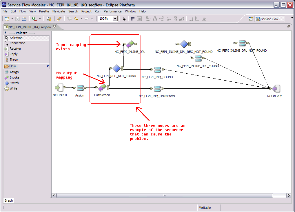
The resulting problem that occurs when you generate runtime code from a
flow like this for the CICS Integrator Adapter for z/OS runtime is that the
Service Flow Modeler Technology Preview does not generate runtime code for the
second node in the sequence. Usually the COBOL program that is
generated compiles without errors. However, at least one paragraph that
you would expect to be present in the COBOL program is missing. One way
to spot this problem is to look for a gap in the normal sequence of
paragraphs. For example, if the following sequence of paragraphs
occurs: 1010-, 1030-, 1040-, 1050-, and so on, then the fact that
paragraph 1020- is omitted indicates that output code is missing.
To work around this problem, modify the sequence of three consecutive nodes
by creating a different but functionally equivalent sequence of nodes.
For example, you can insert an Assign node between the first and second nodes
or between the second and third nodes. The Assign node does not have to
contain any mapping.
If the first node or the second node in the sequence is an Invoke node,
then you can work around this problem by adding an output mapping (which can
be empty) to the first or second node that is an Invoke node:
- Right-click on the output terminal of the Invoke node.
- Click Open Mappings.
- Wait for the mapping editor to open.
- You do not have to create a mapping inside the mapping file.
- Save the mapping file and close the mapping editor.
- Additional requirements with the Startup Transaction Data
property
This note concerns the Startup Transaction Data property. This
property appears in the Generation Properties Editor (when you have just
created a new generation properties file, or when you are editing an existing
generation properties file), on the Node Properties page, in the FEPI Flow
Properties group or in the 3270 Bridge Flow Properties group.
If you are using the Startup Transaction Data property with a terminal
(screen-based) application, and you are using the Service Flow Modeler to
generate runtime code for the CICS Integrator Adapter for z/OS runtime, then
you must do the following in the flow from which you are generating the
runtime code:
- The first Invoke node after the Receive node MUST be for the screen that
results from running the CICS Transaction specified in the Startup Transaction
Data generation property.
- This Invoke node MUST also be the first Invoke node that you added to the
flow when the flow was created or edited.
These requirements are necessary to insure that the proper screen
recognition code is generated after the transaction is executed.
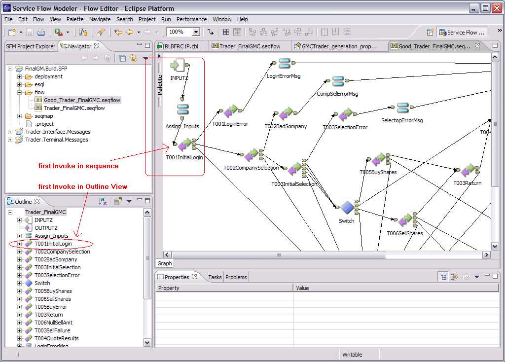
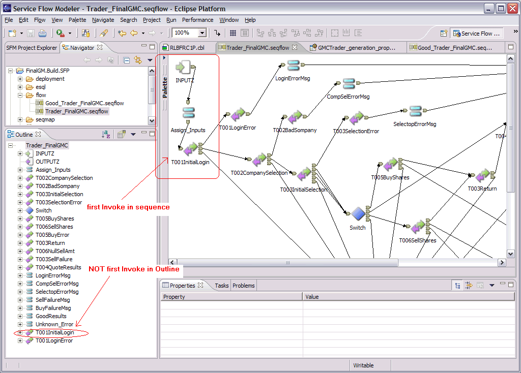
You can visually verify that these requirements have been met:
- In the flow editor, verify that the first Invoke node after the Receive
node is the Invoke node representing the screen that results from running the
CICS Transaction specified in the Startup Transaction Data generation
property.
- While the flow editor is open, in the Outline view, verify that the first
node in the tree with an Invoke symbol is the Invoke node representing the
screen that results from running the CICS Transaction specified in the Startup
Transaction Data generation property.
In the following example, both requirements are met, and the runtime code
will be generated correctly:
In contrast, in the following example, the second requirement is not
met. Consequently the runtime code will not be generated correctly and
you will get unexpected runtime results:
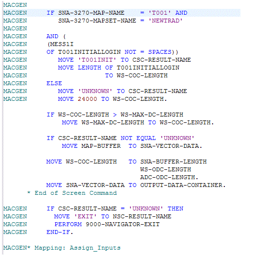
The following illustration shows the correctly generated code for the first
example above:
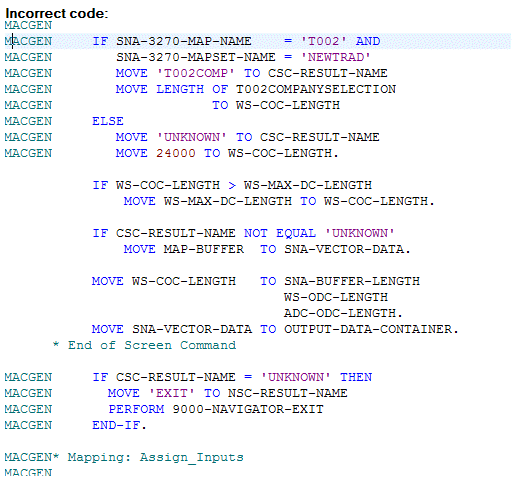
The next illustration shows the incorrectly generated code for the second
example above:
- Adding an IN message_name REFERENCE message_type statement
to the ESQL MODULE for a Switch node
This subsection describes how to add an IN message_name REFERENCE
message_type statement to the ESQL MODULE for a Switch node.
Before you start to perform the steps below, you should already have the
following resources available:
- A flow (for example, Flow01.seqmap).
- The flow should be present in the Flows folder of your service flow
project.
- The flow should contain a Switch node to which you want to add an ESQL
MODULE containing an IN message_name REFERENCE message_type
statement.
- A message file (for example, myMessages.mxsd) containing a message
(for example, msgSwitch01 with a message type of customerName).
- The message file should be present in the Messages subfolder of the
interface definition folder of your service flow project.
- The message file should contain the message that you want to use in the
IN message_name REFERENCE message_type statement.
To add an IN message_name REFERENCE message_type statement to
the ESQL MODULE for a Switch node:
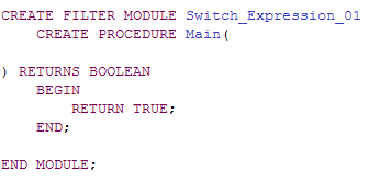
- Add an empty expression to the Switch node:
- Use the flow editor to open the flow.
- In the flow editor, right-click the Switch node, and then click Add
Expressions. The Node Properties - Switch window opens.
- In the Node Properties - Switch window, add an expression to the Reply
Message area:
- If you have not previously added an expression to the Node Properties for
this Switch node, then the Reply Message area of the window contains one
expression with the default name Expression.
- Select the expression. The line becomes an input area.
- Type the name that you want to use for the expression, such as
Expression_01.
- Click OK to close the Node Properties - Switch window.
- If you have previously added one or more expressions to the Node
Properties for this Switch node, then the Reply Message area of the window
displays the names of those expressions.
- Click Add to add a new expression.
- Type the name that you want to use for the expression, such as
Expression_01.
- Click OK to close the Node Properties - Switch window.
- Leave the flow editor open.
- Create an ESQL MODULE for the expression:
- In the flow editor, right-click the Switch node, and then click
ESQL -> Open ESQL ->
Expression_01, where Expression_01 is the name of the
expression that you created in Step i above.
Note: The importance of doing the ESQL -> Open ESQL
operation now:
- You must do the ESQL -> Open ESQL operation at
this point, before you do the ESQL -> Add ESQL
Message operation in Step iii below.
- If you do the ESQL -> Add ESQL Message
operation in Step iii below without ever having done an ESQL
-> Open ESQL operation, then the Service Flow Modeler creates
an ESQL MODULE framework for the Switch node but does not add to it the
IN message_name REFERENCE message_type statement that you
specify. You will have to come back to this step and do the steps in
the order described here.
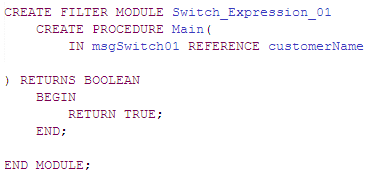
- The Service Flow Modeler automatically creates an ESQL MODULE framework
for the expression that you created in the previous step. The ESQL
editor automatically opens the ESQL file and displays the contents:
- In the ESQL editor, type Ctrl-S to save the contents of the ESQL
file.
Note: The importance of typing Ctrl-S now:
- If this is the first message that you are adding to the ESQL
MODULE for this Switch node, then you must type Ctrl-S at this
point in the procedure. Otherwise, when you perform Step iii below, the
IN message_name REFERENCE message_type statement will not be added
to the ESQL MODULE.
- In contrast, if you have already successfully added a message to the ESQL
MODULE for this Switch node, and you are now adding an additional message to
the same ESQL MODULE, then you do not need to type Ctrl-S at this point in the
procedure. You can add an additional message without having to save the
ESQL file before each addition.
- Leave the ESQL editor open.
- Add an IN message_name REFERENCE message_type statement to the
ESQL MODULE for the Switch node:
- In the flow editor, right-click the Switch node and then click
ESQL -> Add ESQL Message ->
Expression_01, where Expression_01 is the name of the
expression that you created in Step i above. The Add Message Schemas
window opens.
- In the left pane of the Add Message Schemas window, expand the resources
tree and select the message file that you want to use (for example,
myMessages.mxsd).
- In the right pane of the Add Message Schemas window, select the name of
the message that you want to use (for example, msgSwitch01).
- Click Finish. The Add Message Schemas window
closes.
- The Service Flow Modeler automatically adds the IN message_name
REFERENCE message_type statement to the ESQL MODULE for the Switch
node:
Note: After you have added the first message to the ESQL MODULE for the Switch
node, you can add an additional message to the same ESQL MODULE as
follows:
- Skip Step i above, because you have already created the expression.
- Skip Step ii above, because you have already created an ESQL MODULE
framework for the Switch node. Optionally, you can type Ctrl-S to save
the current contents of the ESQL file.
- Perform Step iii above.
- Adding an IN message_name REFERENCE message_type statement
to the ESQL MODULE for a While node
This subsection describes how to add an IN message_name REFERENCE
message_type statement to the ESQL MODULE for a While node.
Before you start to perform the steps below, you should already have the
following resources available:
- A flow (for example, Flow01.seqmap).
- The flow should be present in the Flows folder of your service flow
project.
- The flow should contain a While node to which you want to add an ESQL
MODULE containing an IN message_name REFERENCE message_type
statement.
- A message file (for example, myMessages.mxsd) containing a message
(for example, msgWhile01 with a message type of customerName).
- The message file should be present in the Messages subfolder of the
interface definition folder of your service flow project.
- The message file should contain the message that you want to use in the
IN message_name REFERENCE message_type statement.
To add an IN message_name REFERENCE message_type statement to
the ESQL MODULE for a While node:
- Create an ESQL MODULE for the While node:
- In the flow editor, right-click the While node, and then click
ESQL -> Open ESQL.
Note: The importance of doing the ESQL -> Open ESQL
operation now:
- You must do the ESQL -> Open ESQL operation at
this point, before you do the ESQL -> Add ESQL
Message operation in Step ii below.
- If you do the ESQL -> Add ESQL Message
operation in Step ii below without ever having done an ESQL
-> Open ESQL operation, then the Service Flow Modeler creates
an ESQL MODULE framework for the While node but does not add to it the IN
message_name REFERENCE message_type statement that you specify.
You will have to come back to this step and do the steps in the order
described here.
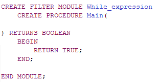
- The Service Flow Modeler automatically creates an ESQL MODULE framework
for the While node. The ESQL editor automatically opens the ESQL file
and displays the contents:
- In the ESQL editor, type Ctrl-S to save the contents of the ESQL
file.
Note: The importance of typing Ctrl-S now:
- If this is the first message that you are adding to the ESQL
MODULE for this While node, then you must type Ctrl-S at this point
in the procedure. Otherwise, when you perform Step ii below, the
IN message_name REFERENCE message_type statement will not be added
to the ESQL MODULE.
- In contrast, if you have already successfully added a message to the ESQL
MODULE for this While node, and you are now adding an additional message to
the same ESQL MODULE, then you do not need to type Ctrl-S at this point in the
procedure. You can add an additional message without having to save the
ESQL file before each addition.
- Leave the ESQL editor open.
- Add an IN message_name REFERENCE message_type statement to the
ESQL MODULE for the While node:
- In the flow editor, right-click the While node and then click
ESQL -> Add ESQL Message. Add Message
Schemas window opens.
- In the left pane of the Add Message Schemas window, expand the resources
tree and select the message file that you want to use (for example,
myMessages.mxsd).
- In the right pane of the Add Message Schemas window, select the name of
the message that you want to use (for example, msgWhile01).
- Click Finish. The Add Message Schemas window
closes.
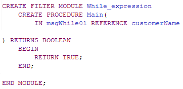
- The Service Flow Modeler automatically adds the IN message_name
REFERENCE message_type statement to the ESQL MODULE for the While
node:
Note: After you have added the first message to the ESQL MODULE for the While node,
you can add an additional message to the same ESQL MODULE as
follows:
- Skip Step i above, because you have already created an ESQL MODULE
framework for the While node. Optionally, you can type Ctrl-S to save
the current contents of the ESQL file.
- Perform Step ii above.