NetView Distribution Manager 1.7
Authors: Margherita De Cesare e Massimo Galluccio
Date: 2001-01-24
Status: draft
Terminology
The following terminology will be used throughout this document.
Tivoli Software Distribution 3.1.5 will be
referred also as SD
Netview Distribution Manager 1.7 will be
referred also as NvDM
Communication Server 6.02 will be
referred also as CS
Introduction
This document illustrates the capability to use a “NvDM 1.7” (an application program designed to use SNA protocols) to communicate with another SNA application (Tivoli Software Distribution 3.1.5) using a TCP/IP transport.
Since NvDM does not have a native support for TCPIP, one of the possible solutions is to use products that convert TCIP datagrams over SNA network and vice versa.
SNA over TCP/IP enables applications using SNA protocols to send and receive information over an IP network. The process of building the unique transmission frame is transparent to NvDM engine. The data, in turn, is passed through the SNA architectural layers and presented to SNA over TCP/IP instead of the usual SNA path control. When VTAM or PC initiates a session for a NvDM transmission, SNA over TCP/IP translates the SNA routing information (fully qualified network name) into IP routing information (IP address) and uses the IP address to create a TCP connection to the appropriate system.
The configuration information you define enables SNA over TCP/IP to determine:
Whether to route the data using SNA transport or to route the data using TCP/IP transport
The IP address associated with the fully qualified LU name
The purpose of this document is to give a real and tested environment, including few documentation tips necessary for customizing the network.
Of course, that does not mean all the other possibilities based on different products, or based on different versions and releases of the products used in this scenario does not work, but means simply we have tested the product on just this configuration.
OSA Adapter used
OSA-Express Gigabit Ethernet (GbE).
Software used
"Enterprise Extender" SNA over TCP/IP requires eNetwork Communications Server for OS/390 V2R8
and DLC Device IBM-EEDLC for Communication Server 6.02
Tivoli Software Distribution 3.1.5
Netview Distribution Manager 1.7
Communications Server/390 2.8
Communication Server 6.02
1. Benefits of Enterprise Extender
Enterprise Extender combines features of SNA and IP to offer the best of both worlds when running SNA traffic over an IP backbone.
Enterprise Extender is particularly suited for customers wishing to exploit the multinode persistent sessions (MNPS) function in a Parallel Sysplex. MNPS allows an application to move between MVS images in a sysplex after a failure, without disrupting existing sessions. Since MNPS utilizes HPR to achieve this, Enterprise Extender is a perfect complement to MNPS even in the situation where there is no SNA backbone network whatsoever. The only requirement is a remote partner node capable of Enterprise Extender (and therefore HPR).
One of the biggest issues facing those who wish to transport SNA over an IP backbone is the question of maintaining SNA’s class of service. In native SNA the class of service specified for a particular session is used to determine both the route taken by the session and the transmission priority allotted to it. With an IP backbone the route is essentially unpredictable because of IP’s connectionless transport. However, IP provides for a transmission priority using the precedence bits in the IP header. Many routers now support the use of these bits, but in the past they have tended to use the TCP or UDP port number as a means of assigning priorities to packets.
Enterprise Extender supports the use of both the precedence bits and the port numbers to inform the IP network of the transmission priority. Use of the precedence bits is recommended because the UDP or TCP port numbers are carried inside the IP datagram, whereas the precedence bits are in the IP header. Thus encrypted packets have unreadable port numbers and fragmented packets have no port numbers after the first fragment; therefore, intermediate routers cannot determine the priority in these cases.
Enterprise Extender has been designed to run over existing IP networks without requiring any change to applications or to IP routers. SNA applications see the same network interface as before.
For more details, see
Migrating Subarea Networks to an IP Infrastructure Using Enterprise Extender (redbook) SG24-5957-00.
1. Configuration
Figure 1 illustrates a simple IP network where NVDM 1.7 communicates with Windows 2000 Software Distribution 3.1.5. VTAM and TCP/IP for MVS must be installed on Node. Communication Server 6.1 must be installed on Windows 2000.
1.1 Managing SNA over TCP/IP
The SNA over TCP/IP support allows IP devices to be addressed using LU names. In the domain name server (DNS) database or in the local HOSTS file, a fully qualified LU name is added to a user-specified IP subdomain name to form the full IP domain name. The IP name is mapped to an IP address used to route network data. Because the IP domain name contains an LU name, TCP/IP commands can now work with LU names defined in the DNS file to test network connections.
VTAM must have a TCP/IP major node defined.
IP network


![]()

Figura 1. VTAM-to-Windows 2000 over an IP network
1.2 Setting Up the Gigabit Ethernet Feature
1.2.1 Setting Up TRLE Statement for OS/390 Communications Server
Follow these instructions for each logical partition planned to use the OSA.
A TRLE (transport resource list) statement is required for the OSA-Express to transfer data using TCP/IP.
To define a transport resource list major node, include the following definition statements:
One VBUILD definition statement to begin the transport resource list major node.
One transport resource list element(TRLE) definition statement for each OSA-Express Gigabit Ethernet.
Use the following example as a reference.
* ======================================================================*
* TRL MAJOR NODE FOR GB ETHERNET CHPID F0 *
* ======================================================================*
TRLEF0 VBUILD TYPE=TRL
MTRLEF0 TRLE LNCTL=MPC,
READ=(222),
WRITE=(223),
DATAPATH=(224),
PORTNAME=OSAGEF0,
MPCLEVEL=QDIO
Specify a TRL name of your choice in place of MTRLEF0. To avoid a naming conflict, the TRL name must not match the VTAMLST member name containing this Transport Resource List Major Node, and must be unique across all users of a single OSA-Express feature.
TRLE and LNCTL=MPC are required.
Specify one number for the READ device, one for the WRITE, and one DATAPATH device number for each instance of TCP/IP in the logical partition. These device numbers must be defined in the hardware configuration.
Enter a PORTNAME of your choice. This must be the same for all users.
MPCLEVEL=QDIO is a required entry.
Activate the TRL deck, which contains the TRLE definition.
Example: V NET,ID=TRLE24F0,ACT,UPDATE=ALL
1.2.2 Updating the TCP/IP Profile for OS/390 Communications Server
TCP/IP uses the OSA
as a multipath channel (MPC) device. This requires that you define a device
statement, link statement, and home statement in the TCP/IP profile. The
following instructions provide the minimum details for updating the TCP/IP
profile.
1. Edit the TCP/IP profile. Within the Hardware Definitions section of the profile, add a device statement and a link statement using the following instructions.
; ======================================================================
; OSAGEF0
; ======================================================================
DEVICE OSAGEF0 MPCIPA NONROUTER
LINK OSAGEF0LNK IPAQGNET OSAGEF0
; ======================================================================
; HOME addresses
; ======================================================================
HOME
146.84.90.22 OSAGEF0LNK
; ======================================================================
; Direct Routes - Routes that are directly connected to my interfaces.
; ======================================================================
GATEWAY
; Network First Hop Link Name Packet Size Subnet Mask Subnet Value
146.84 = OSAGEF0LNK 1500 0.0.255.0 0.0.90.0
; ======================================================================
; Start all the defined devices.
; ======================================================================
START OSAGEF0
1) Define one
DEVICE statement for the OSA port.
DEVICE device_name MPCIPA NOROUTER |
device_name
Specify a device name. The name must be the same name that you specified for
the PORTNAME in the TRLE statement.
MPCIPA
Specifies that the device belongs to the multipath channel (MPC) family of
interfaces and uses the IP assist based interface.
NONROUTER
The OSA-Express Gigabit Ethernet feature does not forward unknown packets.
2) Define one LINK statement for the OSA port.
LINK link_name IPAQGNET device_name
link_name
Specify a name for this link. The maximum length is 16 characters. This name is
also used in the home statement.
IPAQGNET
Required entry that indicates that the link uses the IP Assist interface,
belongs to the QDIO family of interfaces, and uses the Gigabit Ethernet
protocol.
device_name
Specify the same name you used in the device statement and for the PORTNAME in
the TRLE statement.
3) Define the Home IP address of each link.
HOME internet_address link_name
internet_address
Specify an IP address for this link in the form x.x.x.x.
link_name
Specify the link name you choose in the link statement.
4) Define the routes using direct (static) routes through the GATEWAY statement or use the RouteD router daemon to do it dynamically.
5) Define one START command for each OSA device.
After the TCP/IP
profile is updated and started you can check that the devices were started. The
following command checks the read, write and data devices (assuming device
numbers 222-224).
d u,,,222
If all is OK, you will see for the read, write, and data devices, respectively:
222 A-BSY
223 A
224 A-BSY
For more details, see “OSA-Express Guide and Reference” and “S/390 OSA-Express Implementation Guide” (red book)
1.3 VIPA configuration
Virtual IP Addressing (VIPA) is an availability feature available on Communications Server for OS/390 TCP/IP. This function is designed to increase availability and provide a more robust network. VIPA allows the configuration of a virtual IP address and link. Because this virtual interface does not truly exist it never suffers a failure. The virtual address is actually associated with the TCP/IP stack and not any real physical interface. The other hosts see the virtual interface (IP address) as an additional hop from the interfaces that are on this CS for OS/390 hosts. As long as the mainframe has anyinterfaces active, it can still recover from an interface failure by advertising routes to the VIPA over some other interface. Following figure shows how we defined our VIPA device and link in the TCPIP profile. The device and adapter number are ignored but required for compatibility with other device types.
; ======================================================================
; Virtual IP adrress for msysp24 image
;
======================================================================
DEVICE
VIPA01 VIRTUAL 0
LINK LVIPA1 VIRTUAL 0 VIPA01
LVIPA1 specifies a name for this link. This name is also used in the home statement.
The VIPA address must be added to the home statement in the TCPIP profile.
; ======================================================================
; HOME addresses
; ======================================================================
HOME
146.84.90.22 OSAGEF0LNK
146.84.90.250 LVIPA1
1.4 Enterprise Extender configuration
1.4.1 TCP/IP configuration changes
This chapter shows how we have implemented Enterprise Extender links within our network. The Enterprise Extender connection to VTAM also requires a device and link definition. It uses the same interface as to another TCP/IP stacks on the same OS/390 image, known as Samehost. TCP/IP recognizes the name IUTSAMEH as being a Samehost interface, and treats it in a similar fashion to an MPC connection, hence the device type MPCPTP. The name IUTSAMEH is mandatory.
; ====================================================================
; VTAM to TCP/IP stack
; ====================================================================
;
DEVICE IUTSAMEH MPCPTP
LINK EELINK MPCPTP IUTSAMEH
START IUTSAMEH
EELINK specifies a name for this link. This name is also used in the home statement.
In the HOME statement we also defined an IP address for our link named EELINK
; ======================================================================
; HOME addresses
; ======================================================================
HOME
146.84.90.22 OSAGEF0LNK
146.84.90.250 LVIPA1
146.84.90.251 EELINK
1.4.2 Defining Enterprise Extender
The NODETYPE option in the VTAM start options must be coded as NN if this VTAM is to act as a network node server (NNS) or a dependent LU server (DLUS) for other nodes.
Next, we defined the Enterprise Extender port itself. This is doing using an XCA major node as shown in the following figure:
* =============================================
* XCA MAJOR NODE ENTERPRISE EXTENDER
* =============================================
EE24SW VBUILD TYPE=XCA
*
EE24PORT PORT MEDIUM=HPRIP,
SAPADDR=08,
LIVTIME=10,
IPTOS=(20,40,80,C0),
IPPORT=12000,
SRQTIME=15,
SRQRETRY=3
EE24GRP GROUP DIAL=YES,
DYNPU=YES,
DYNPUPFX=EX,
AUTOGEN=(16,EEL,EEP),
CALL=INOUT
TYPE = XCA This identifies to VTAM that it is an XCA major node.
MEDIUM=HRPIP This tells VTAM this is an Enterprise Extender connection rather than an Ethernet or ATM connection.
DIAL=YES Since Enterprise Extender connections use switched protocols between APPN nodes, dial=yes is required to accomplish this.
Next we created switched major nodes for our links to the CS (or PC) for Windows:
*=============================================
* SWITCHED MAJOR NODE TO DEFINE END NODES
* ENTERPRISE EXTENDER
*=============================================
EE24SWMN VBUILD TYPE=SWNET,MAXNO=10,MAXGRP=10
*
EEXSWP65 PU PUTYPE=2,NETID=ITIBM0PC,CPNAME= I9RLO02B,TGN=3,
CPCP=YES,
CONNTYPE=APPN,
HPR=YES,DWACT=NO,
TGP=ETHERNET,ISTATUS=ACTIVE
EEXPTH65 PATH IPADDR=146.84.90.249,GRPNM=EE24GRP
The GRPNM keyword ties back to the XCA major node. The IPADDR is the address of end node; the CPNAME is its control point name.
Activate the Major Nodes EE24SW
Example: V NET,ID=EE24SW,ACT,SCOPE=ALL
And EE24SWMN
Example: V NET,ID=EE24SWMN,ACT,SCOPE=ALL
For more details, see
OSA-Express Guide and Reference SA22-7403-00,
S/390 OSA-Express Implementation Guide (redbook) SG24-5948-00,
Migrating Subarea Networks to an IP Infrastructure Using Enterprise Extender (redbook) SG24-5957-00.
1.5 Communication Server 6.02 Setting
For this scenario it is assumed that:
The workstation is connected with the host via Ethernet
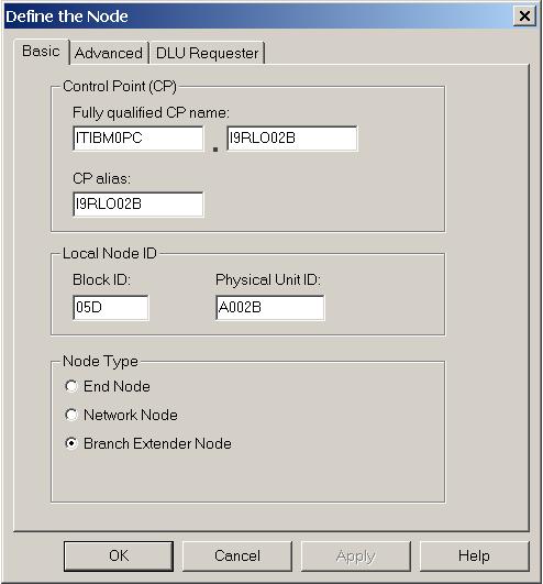
CP Name is I9RLO02B
Network name is ITIBM0PC
Local Node ID is 05D-A002B
Partner CP name is MVSESA24
Partner Network name is ITIBM0PC
Partner remote address is 146.84.90.250
Configuration File name is EECTCP2.acg
We refer to the SD 3.1.5 manuals for every details. All panels not described here are unchanged from the SD 3.1.5 "Quick Beginnings" on line manual.
1) Add a new node (see SD 3.1.5 "Quick Beginnings" on-line manual);
2) From the Configuration options list box shown in Communications Server SNA Node Configuration Window select
Configure Devices.
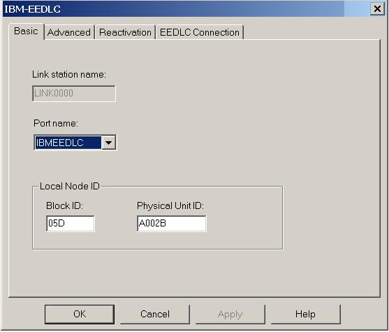
From the DLCs list box select IBM-EEDLC then New.
1) Add a new node; select the Branch Extender Node.
.
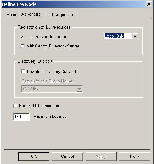
2) Set the Advanced parameters:
3) Create a new link:
4) Set the advanced link parameters
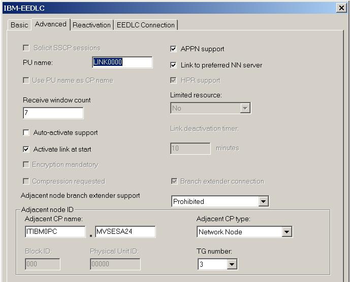
The Adjacent CP name is the CP of the HOST. The type of CP should be "Network Node". The TG number should be 3. The PU name and the name of the link session should be the same.
5) Set the EEDLC connection parameters
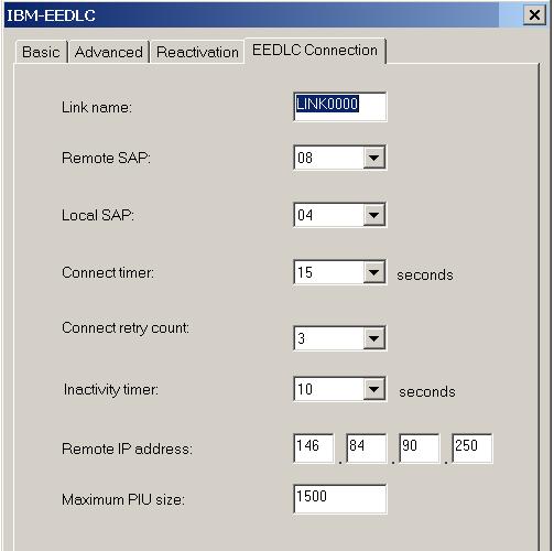
The Remote SAP should be 08. The Remote IP address is the address of the HOST.