DB2 Connect Quick Beginnings for UNIX**
Use the completed worksheet in Table 16 to configure DB2 Connect APPC
communications for access to a remote host or AS/400 database server.

| Go to the sections that describe how to configure APPC communications on
the platforms that are present in your network:
|
This section describes how to configure IBM eNetwork Communication Server
V5.0.3 for AIX on your DB2 Connect workstation to connect to
host or AS/400 database servers using APPC. IBM eNetwork Communication
Server for AIX is the only SNA product supported for DB2 Connect running on
RS/6000 machines.
Before you begin, ensure that your workstation has IBM eNetwork
Communication Server V5.0.3 for AIX (CS/AIX) installed.
If you need further information in order to configure your SNA environment,
refer to the online help provided with CS/AIX.
The following assumptions are made:
- The basic installation of the IBM eNetwork Communication Server V5 for AIX
package has already been completed and PTF 5.0.3 has been
applied.
- DB2 Connect has been installed.
To configure CS/AIX for use by DB2 Connect, log on to the system as a user
with root authority and use either the /usr/bin/snaadmin
program or the /usr/bin/X11/xsnaadmin program. Information
about these programs can be found in the system documentation. The
following steps describe how to use the xsnaadmin program to
configure CS/AIX.
Step 1.
| Enter the command xsnaadmin. The Node window for the
server opens.
|
Step 2.
| Define a node.
- Select Services --> Configure Node Parameters.
The Node Parameters window opens.
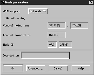
- Select End node from the APPN support drop-down
menu.
- Enter your network ID and the local PU name ((9) and (10))
in the Control point name fields.
- Enter the local PU name ((10)) in the Control point
alias field.
- Enter your Node ID ((13) and (14)) in the Node ID
fields.
- Click OK.
|
Step 3.
| Define a port.
- Select the Connectivity and Dependent LUs window.
- Click the Add push button. The Add to Node window
opens.
- Select the Port using radio button.
- Click the Port Using drop down box and select the appropriate
port type. For the purpose of our example, we will select the
Token ring card option.
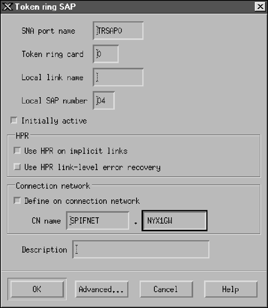
- Click OK. The Port window for the chosen port type
opens.
- Enter a name for the port in the SNA port name field.
- Select the Initially active check box.
- From the Connection network box, select Define on
connection network check box.
- Enter your SNA Network Name ((9)) in the first part of the CN
name field.
- Enter the Local PU Name ((10)) associated with your AIX computer in
the second part of the CN name field.
- Click OK. The Port window closes and a new port opens in
the Connectivity and Dependent LUs window.
|
Step 4.
| Define a link station.
- In the Connectivity and Dependent LUs window, select the port that you
defined in the previous step.
- Click the Add push button. The Add to Node window
opens.
- Select the Add a link station to port radio button.
- Click OK. The Token ring link station window
opens.
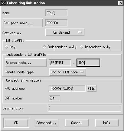
- Enter a name for the link in the Name field.
- Click the Activation drop-down box and select the On
demand option.
- Select the Independent only option in the LU traffic
box.
- In the Independent LU traffic box:
- Enter the network ID ((3)) and the partner LU name ((2)) in
the Remote node fields.
- Click the Remote node type drop-down box and select the type of
node that applies to your network.
- In the Contact information box, enter the SNA destination
address ((8)) assigned for the host or AS/400 system in the Mac
address field.
- Click OK. The Link Station window closes and a new link
station appears in the Connectivity and Dependent LUs window.
|
Step 5.
| Define a local LU.
- Select the Independent local LUs window.
- Click the Add push button. The Local LU window
opens.
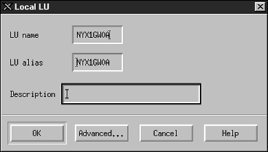
- Enter your independent local LU Name ((11)) in the LU
name field.
- Enter the same name in the LU alias field ((12)).
- Click OK. The new LU appears in the Independent Local
LUs window.
|
Step 6.
| Define a partner LU over the link station.
- Select Services --> APPC --> New PLUs -->Over
Link Station from the menu bar. The Partner LU on link station
window opens.
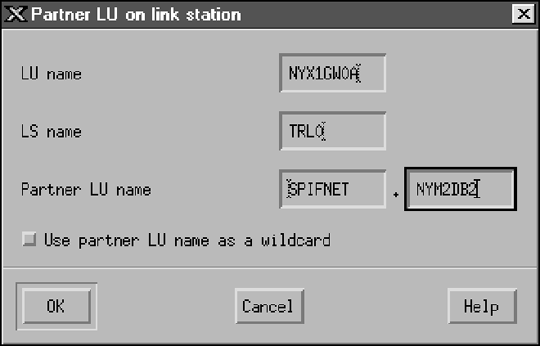
- Enter the name for the local LU ((11)) you defined previously in
the LU name field.
- Enter the name for the link station you defined previously in the LS
name field.
- Enter the name of the partner LU you want to connect to ((2)) in
the Partner LU name field.
- Click OK. The Partner LU appears in the Independent
Local LUs window of the Local LU that was created in the previous step.
|
Step 7.
| Define an alias for the partner LU.
- Select the Remote Systems window.
- Click the Add push button. The Add to Node window
opens.
- Select the Define partner LU alias radio button.
- Click OK. The Partner LU window opens.
- Enter an alias for the partner LU in the Alias field.
- Enter the same value in the Uninterpreted name field.
- Click OK.
|
Step 8.
| Define a mode.
- Select Services --> APPC--> Modes from the menu
bar. The Modes window opens.
- Click the New push button. The Mode window opens.
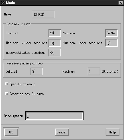
- Enter a mode name ((15)) in the Name field.
- The configuration values below are suggested for the following
fields:
- Initial session limits: 20
- Maximum session limits: 32767
- Min con. winner sessions: 10
- Min con. loser sessions: 10
- Auto-activated sessions: 4
- Initial receive pacing window: 8
These values are suggested because they are known to work. You will
need to tailor these values so that they are optimized for your particular
application environment.
- Click OK. The new mode appears in the Modes
window.
- Click Done.
|
Step 9.
| Define the CPI-C destination name.
- Select Services --> APPC--> CPI-C from the menu
bar. The CPI-C destination names window opens.
- Click the New push button. The CPI-C destination window
opens.
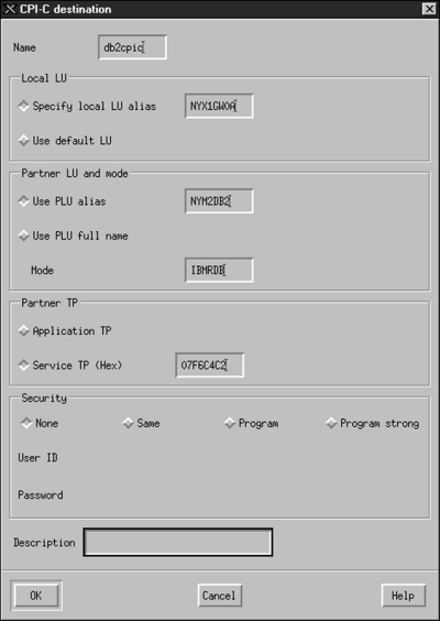
- In the Name field, enter the Symbolic Destination Name
((16)) you want to associate with the host or AS/400 server
database. This example uses db2cpic.
- In the Partner TP box:
- For DB2 for MVS/ESA, DB2 for OS/390, and DB2 for AS/400, select the
Service TP (hex) radio button, and enter the hexadecimal TP number
((17)). (For DB2 Universal Database for OS/390 or DB2/MVS, you
can also use the default application TP DB2DRDA. For DB2 for
AS/400 you can also use the default application TP
QCNTEDDM.)
- For DB2 for VM or VSE, select the Application TP radio
button. For DB2 for VM, enter the DB2 for VM database name. For
DB2 for VSE, enter the AXE as the application TP ((17)).
- In the Partner LU and mode box:
- Select the Use PLU alias radio button, and enter the partner LU
alias ((2)) you created in a previous step.
- In the Mode field, enter the mode name ((15)) for the
mode that you created in a previous step.
- In the Security box, select the radio button that corresponds
to the type of security level that you want to run on your network.
- Click OK. The new destination name appears in the
Destination Names window.
- Click Done.
|
Step 10.
| Test the APPC connection.
- Start the SNA subsystem by entering the /usr/bin/sna start
command. You can enter the /usr/bin/sna stop command to stop
the SNA subsystem first, if required.
- Start the SNA administration program. You can enter either the
/usr/bin/snaadmin command or the /usr/bin/X11/xsnaadmin
command.
- Start the subsystem node. Select the appropriate node icon in the
button bar, and click the Start push button.
- Start the link station. Select the link station you defined
previously in the Connectivity and Dependent LUs window, and click the
Start push button.
- Start the session. Select the LU you defined previously in the
Independent Local LUs window, and click the Start push
button. A session activation window opens.
- Select or enter a partner LU and mode.
- Click OK.
|

| You may also need to contact your database or network administrators to
have your local LU names added to the appropriate tables in order to access
the host or AS/400 server database.
|

| You now need to update the DB2 directories, bind utilities and
applications to the server, and test the connection.
Go to 3. Catalog the APPC Node.
|
This section describes how to configure Bull DPX/20 SNA/20
Server on your DB2 Connect workstation to connect to host or AS/400 database
servers using APPC. If Bull DPX/20 SNA/20 Server is installed prior to
installing DB2 Connect, DB2 Connect uses Bull SNA. Otherwise, you need
to configure DB2 Connect to work with IBM eNetwork Communications Server
V5.0.3 for AIX. See Configuring IBM eNetwork Communication Server for AIX for more information.
To determine if Bull SNA is installed on your AIX 4.2 (or later)
system, enter the following command:
lslpp -l express.exsrv+dsk
If Bull SNA is installed, you will see output similar to the
following:
    Fileset                      Level  State      Description
    ----------------------------------------------------------------------
  Path: /usr/lib/objrepos
    express.exsrv+dsk          2.1.3.0  COMMITTED  EXPRESS SNA Server and
                                                   Integrated Desktop
If you install Bull SNA after installing DB2 Connect and you want DB2
Connect to use Bull SNA instead of IBM eNetwork Communications Server for AIX,
log on to the system as a user with root authority and enter the
following command:
/usr/lpp/db2_06_01/cfg/db2cfgos
If you want to install the Bull DPX/20 SNA/20 Server, then you must have
the following software:
__ 1.
| AIX V4.1.4
|
__ 2.
| Express SNA Server V2.1.3
|
For more information on setting up your SNA environment, refer to the Bull
DPX/20 SNA/20 Server Configuration Guide.
DB2 Connect, when used with the Bull SNA server, cannot have inbound APPC
connections from remote clients. The only APPC connections it can have
are outbound APPC connections to the host.
To configure Bull SNA for use by DB2 Connect, enter the express
command to configure the following SNA parameters:
     Config         Express           Default configuration for EXPRESS
      Node          NYX1              SPIFNET.NYX1 (HOSTNAME=NYX1)
       Indep. LUs   6.2 LUs Using All Stations
         LU         NYX1              Control Point LU
       Link         tok0.00001        Link (tok0)
        Station     MVS               To MVS from NYX1
         LU         NYX1GW01          To MVS from NYX1
          LU Pair   NYM2DB2           To MVS from NYX1
           Mode     IBMRDB            IBMRDB
Use default values for fields not listed.
The following example illustrates the sample configuration:
   Defining hardware:

   System (hostname) = NYX1
   Adapter and Port  = NYX1.tok0
     MAC Address     = 400011529778

   Defining SNA node:

   Name          = NYX1
   Description   = SPIFNET.NYX1 (HOSTNAME=NYX1)
   Network ID    = SPIFNET
   Control Point = NYX1
   XID Block     = 05D
   XID ID        = 29778

   Defining token ring link:

   Name            = tok0.00001
   Description     = Link (tok0)
   Connection Network name
     Network ID    = SPIFNET
     Control Point = NYX

   Defining token ring station:

   Name               = MVS
   Description        = To MVS from NYX1
   Remote MAC address = 400009451902
   Remote Node name
     Network ID       = SPIFNET
     Control Point    = NYX

   Defining Local LU 6.2:

   Name        = NYX1GW01
   Description = To MVS from NYX1
   Network ID  = SPIFNET
   LU name     = NYX1GW01

   Defining Remote LU 6.2:

   Name                 = NYM2DB2
   Description          = To MVS from NYX1
   Network ID           = SPIFNET
   LU name              = NYM2DB2
   Remote Network ID    = SPIFNET
   Remote Control Point = NYX
   Uninterpreted Name   = NYM2DB2

   Defining Mode:

   Name             = IBMRDB
   Description      = IBMRDB
   Class of service = #CONNECT

   Defining Symbolic Destination Info:

   Name        = DB2CPIC
   Description = To MVS from NYX1
   Partner LU  = SPIFNET.NYM2DB2
   Mode        = IBMRDB
   Local LU    = NYX1GW01
   Partner TP  = DB2DRDA
After you have configured these SNA parameters, you must stop and start the
SNA server. To do this, perform the following steps:
Step 1.
| Log on to the system as a user with root authority.
|
Step 2.
| Make sure your PATH contains the $express/bin
(/usr/lpp/express/bin)entry.
|
Step 3.
| Check for active users before stopping the server by entering the
following command:
express_adm shutdown
|
Step 4.
| Stop all EXPRESS activity by entering the following command:
express_adm stop
|
Step 5.
| Start EXPRESS by entering the following command:
express_adm start
|

| You now need to update the DB2 directories, bind utilities and
applications to the server, and test the connection.
Go to 3. Catalog the APPC Node.
|
This section describes how to configure SNAplus2 for HP-UX on your DB2
Connect workstation to connect to host or AS/400 database servers using
APPC. SNAplus2 for HP-UX is the only SNA product supported for DB2
Connect running on HP-UX V10 and V11 machines.
Before you begin, ensure that your workstation has HP-UX SNAplus2
installed. If you need more information in order to configure your SNA
environment, refer to the online help provided with SNAplus2.
The following assumptions are made:
- The basic installation of the SNAplus2 for HP-UX package has already been
completed.
- DB2 Connect has been installed.
To configure SNAplus2 for DB2 Connect, log on to the system as a user with
root authority and use either the /opt/sna/bin/snapadmin
program or the /opt/sna/bin/X11/xsnapadmin program.
Information about these programs can be found in the system
documentation. The following steps describe how to use the
xsnapadmin program to configure SNAplus2.
Step 1.
| Enter the command xsnapadmin. The Node window for the
server opens.
|
Step 2.
| Define a node.
- Select Services --> Configure Node Parameters.
The Node Parameters window opens.

- Select End node from the APPN support drop-down
menu.
- Enter your network ID and the local PU name ((9) and (10))
in the Control point name fields.
- Enter the local PU name ((10)) in the Control point
alias field.
- Enter your Node ID ((13) and (14)) in the Node ID
fields.
- Click OK.
|
Step 3.
| Define a port.
- Select the Connectivity and Dependent LUs window.
- Click the Add push button. The Add to Node window
opens.
- Select the Port using radio button.
- Click the Port Using drop down box and select the appropriate
port. For the purpose of our example, we will select the Token
ring card option.
- Click OK. The Port window for the chosen port type
opens.
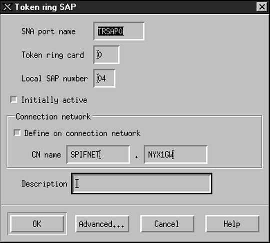
- Enter a name for the port in the SNA port name field.
- Select the Initially active check box.
- Select the Define on a connection network check box.
- Enter your network ID ((9)) in the first part of the CN
name field.
- Enter your local control point name ((10)) in the second part of
the CN name field.
- Click OK. The Port window closes and a new port appears
in the Connectivity and Dependent LUs window.
|
Step 4.
| Define a link station.
- In the Connectivity and Dependent LUs window, select the port that you
defined in the previous step.
- Click the Add push button. The Add to Node window
opens.
- Select the Add a link station to port radio button.
- Click OK. The Token ring link station window
opens.

- Enter a name for the link in the Name field.
- Click the Activation drop-down box and select the On
demand option.
- Select the Independent only option in the LU traffic
box.
- In the Independent LU traffic box:
- Enter the network ID ((3)) and the partner LU name ((2)) in
the Remote node fields.
- Click the Remote node type drop-down box and select the type of
node that applies to your network.
- In the Contact information box, enter the SNA destination
address ((8)) assigned for the host or AS/400 system in the Mac
address field.
- Click OK. The Link Station window closes and a new link
station appears in the Connectivity and Dependent LUs window.
|
Step 5.
| Define a local LU.
- Select the Independent local LUs window.
- Click the Add push button. The Local LU window
opens.

- Enter your independent local LU Name ((11)) in the LU
name field.
- Enter the same name in the LU alias field ((12)).
- Click OK. The new LU appears in the Independent Local
LUs window.
|
Step 6.
| Define a remote node.
- Select the Remote Systems window.
- Click the Add push button. The Add to Node window
opens.
- Select Define remote node.
- Click OK. The Remote Node configuration window
opens.
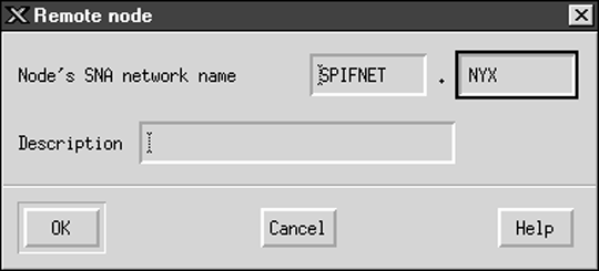
- Enter the network ID ((3)) and the partner LU name ((2)) in
the Node's SNA network name field.
- Click OK. The remote node appears in the Remote Systems
window, and a default partner LU is defined for the node.
|
Step 7.
| Define a partner LU.
- In the Remote Systems window, double-click the default partner LU that was
created when you defined a remote node in the previous step. The
Partner LU window opens.
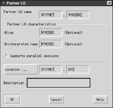
- Enter the same partner LU name ((2)) in the Alias and
Uninterpreted name fields.
- Select Supports parallel sessions.
- Click OK.
|
Step 8.
| Define a mode.
- Select Services --> APPC--> Modes from the menu
bar. The Modes window opens.
- Click the New push button. The Mode window opens.

- Enter a mode name ((15)) in the Name field.
- The configuration values below are suggested for the following
fields:
- Initial session limits: 20
- Maximum session limits: 32767
- Min con. winner sessions: 10
- Min con. loser sessions: 10
- Auto-activated sessions: 4
- Initial receive pacing window: 8
These values are suggested because they are known to work. You will
need to tailor these values so that they are optimized for your particular
application environment.
- Click OK. The new mode appears in the Modes
window.
- Click Done.
|
Step 9.
| Define the CPI-C destination name.
- Select Services --> APPC--> CPI-C from the menu
bar. The CPI-C destination names window opens.
- Click the New push button. The CPI-C destination window
opens.

- In the Name field, enter the Symbolic Destination Name
((16)) you want to associate with the host or AS/400 server
database. This example uses db2cpic.
- In the Partner TP box:
- For DB2 for MVS/ESA, DB2 for OS/390, and DB2 for AS/400, select the
Service TP (hex) radio button, and enter the hexadecimal TP number
((17)). (For DB2 Universal Database for OS/390 or DB2/MVS, you
can also use the default application TP DB2DRDA. For DB2 for
AS/400 you can also use the default application TP
QCNTEDDM.)
- For DB2 for VM or VSE, select the Application TP radio
button. For DB2 for VM, enter the DB2 for VM database name. For
DB2 for VSE, enter the AXE as the application TP ((17)).
- In the Partner LU and mode box:
- Select the Use PLU alias radio button, and enter the partner LU
alias ((2)) you created in a previous step.
- In the Mode field, enter the mode name ((15)) for the
mode that you created in a previous step.
- In the Security box, select the radio button that corresponds
to the type of security level that you want to run on your network.
- Click OK. The new destination name appears in the
Destination Names window.
- Click Done.
|
Step 10.
| Test the APPC connection.
- Start the SNA subsystem by entering the /opt/sna/bin/sna start
command. You may need to enter the /opt/sna/bin/sna stop
command to stop the SNA subsystem first.
- Start the SNA administration program. You can use either the
/opt/sna/bin/snaadmin command or the
/opt/sna/bin/X11/xsnaadmin command.
- Start the subsystem node. Select the appropriate node icon in the
button bar, and click the Start push button.
- Start the link station. Select the link station you defined
previously in the Connectivity and Dependent LUs window, and click the
Start push button.
- Start the session. Select the LU you defined previously in the
Independent Local LUs pane, then click the Start button. A
session activation window opens. Select or enter a partner LU and
mode.
- Click OK.

| You may also need to contact your database or network administrators to
have your Local LU names added to the appropriate tables in order to access
the host or AS/400 server database.
|
|

| You now need to update the DB2 directories, bind utilities and
applications to the server, and test the connection.
Go to 3. Catalog the APPC Node.
|
This section describes how to configure DCL SNAP-IX V6.0.6
for SPARC Solaris on your DB2 Connect workstation to connect to host or AS/400
database servers using APPC.
Before you begin, ensure that your workstation has DCL SNAP-IX
V6.1.0 for SPARC Solaris installed. For more information
on configuring your SNA environment, refer to the online help provided with
DCL SNAP-IX V6.1.0 for SPARC Solaris.
The following assumptions have been made:
- You have completed the basic installation of the DCL SNAP-IX
V6.1.0 for SPARC Solaris package.
- You have installed DB2 Connect.
To configure DCL SNAP-IX V6.1.0 for SPARC Solaris for DB2
Connect, log on to the system as a user with root authority and use either the
/opt/sna/bin/snaadmin or the /opt/sna/bin/X11/xsnaadmin
program. For more information about these programs, refer to the system
documentation.
To configure DCL SNAP-IX V6.1.0 for SPARC Solaris using the
xsnaadmin program, perform the following steps:
Step 1.
| Enter the xsnaadmin command. The Node window for the
server opens.
|
Step 2.
| Define a node.
- Select Services --> Configure Node Parameters.
The Node Parameters window opens.

- Select End node from the APPN support drop-down
menu.
- Enter your network ID and the local PU name ((9) and (10))
in the Control point name fields.
- Enter the local PU name ((10)) in the Control point
alias field.
- Enter your Node ID ((13) and (14)) in the Node ID
fields.
- Click OK.
|
Step 3.
| Define a port.
- Select the Connectivity and Dependent LUs window.
- Click Add. The Add to Node window opens.
- Select the Port using radio button.
- Click on the Port Using drop down box and select the
appropriate port. For the purpose of our example, we will select the
SunTRI/P Adapter option.
- Click OK. The Port window for the chosen port type
opens.
- Enter a name for the port in the SNA port name field.
- Select the Initially active check box.
- Click OK. The Port window closes, and a new port appears
in the Connectivity and Dependent LUs window.
|
Step 4.
| Define a link station.
- In the Connectivity and Dependent LUs window, select the port that you
defined in the previous step.
- Click Add. The Add to Node window opens.
- Select the Add a Link Station to Port radio button.
- Click OK. The Token Ring Link Station window
opens.
- Enter a name for the link in the Name field.
- Select the Independent Only option in the LU traffic
box.
- In the Independent LU traffic box:
- Enter the Network ID ((3)) and the Partner PU Name ((2)) in
the Remote Node fields.
- Click on the Remote node type drop down box and select the type
of node that applies to your network.
- In the Contact information box, enter the SNA Destination Address
((8)) assigned for the host or AS/400 system in the Mac address
field.
- Click OK. The Link Station window closes, and a new link
station appears in the Connectivity and Dependent LUs pane.
|
Step 5.
| Define a local LU.
- Select the Independent local LUs window.
- Click the Add push button. The Local LU window
opens.

- Enter your independent local LU Name ((11)) in the LU
name field.
- Enter the same name in the LU alias field ((12)).
- Click OK. The new LU appears in the Independent Local
LUs window.
|
Step 6.
| Define a remote node.
- Select the Remote Systems window.
- Click the Add push button. The Add to Node window
opens.
- Select Define remote node.
- Click OK. The Remote Node configuration window
opens.

- Enter the network ID ((3)) and the partner LU name ((2)) in
the Node's SNA network name field.
- Click OK. The remote node appears in the Remote Systems
window, and a default partner LU is defined for the node.
|
Step 7.
| Define a partner LU.
- Select Services --> APPC --> New partner LUs
--> Partner LU on Remote Node from the menu bar. The
Partner LU window opens.
- Enter the Partner LU name in the Partner LU Name fields.
- Enter the same Partner LU name ((2)) in the Alias and
Uninterpreted Name fields.
- Select Supports Parallel Sessions.
- Enter the Partner PU name in the Location fields.
- Click OK.
|
Step 8.
| Define a mode.
- Select Services --> APPC--> Modes from the menu
bar. The Modes window opens.
- Click the New push button. The Mode window opens.

- Enter a mode name ((15)) in the Name field.
- The configuration values below are suggested for the following
fields:
- Initial session limits: 20
- Maximum session limits: 32767
- Min con. winner sessions: 10
- Min con. loser sessions: 10
- Auto-activated sessions: 4
- Initial receive pacing window: 8
These values are suggested because they are known to work. You will
need to tailor these values so that they are optimized for your particular
application environment.
- Click OK. The new mode appears in the Modes
window.
- Click Done.
|
Step 9.
| Define the CPI-C destination name.
- Select Services --> APPC -->CPI-C from the menu
bar. The CPI-C Destination Names window opens.
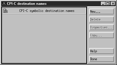
- Click New. The CPI-C Destination window opens.

- Enter the Symbolic Destination Name ((16)) you want to associate
with the host or AS/400 server database in the Name field.
This example uses DB2CPIC.
- In the Local LU box:
- Select the specific Local LU alias radio button and enter the Local LU
alias you created previously.
- In the Partner LU and mode box:
- Select the Use PLU Alias radio button, and enter the Partner LU
Alias ((2)) you created in a previous step.
- Enter the Mode name ((15)) for the mode that you created in a
previous step in the Mode field.
- In the Partner TP Box:
- For DB2 for MVS/ESA, DB2 for OS/390, and DB2 for AS/400, select the
Service TP (hex) radio button.
- Enter the hexadecimal TP number ((17)). (For DB2 Universal
Database for OS/390 or DB2/MVS, you can also use the default application TP
DB2DRDA. For DB2 for AS/400 you can also use the default application TP
QCNTEDDM.)
- For DB2 for VM or VSE, select the Application TP radio
button. For DB2 for VM, enter the DB2 for VM database name. For
DB2 for VSE, enter the AXE as the application TP. ((17))
- In the Security box, select the radio button that corresponds
to the type of security level that you want to run on your network.
- Click OK. The new destination name appears in the
Destination Names window.
- Click Done.
- Test the APPC connection.
- Start the SNA subsystem by entering the /opt/sna/bin/sna start
command. You can enter the /opt/sna/bin/sna stop command to
stop the SNA subsystem first, if required.
- Start the SNA administration program. You can use either the
/opt/sna/bin/snaadmin or the /opt/sna/bin/X11/xsnaadmin
command.
- Start the subsystem node. Select the node icon in the button bar,
and click the Start push button.
- Start the link station. Select the link station that you previously
defined in the Connectivity and Dependent LUs window. Click
Start.
- Start the session. Select the LU you defined previously in the
Independent Local LUs window, then click Start. A session
activation window opens. Select or enter the Partner LU and Mode
desired.
- Click OK.

| You now need to update the DB2 directories, bind utilities and
applications to the server, and test the connection.
Go to 3. Catalog the APPC Node.
|
|
Step 10.
| Test the APPC connection.
- Start the SNA subsystem by entering the /opt/sna/bin/sna start
command. You can enter the /opt/sna/bin/sna stop command to
stop the SNA subsystem first, if required.
- Start the SNA administration program. You can use either the
/opt/sna/bin/snaadmin or the /opt/sna/bin/X11/xsnaadmin
command.
- Start the subsystem node. Select the node icon in the button bar,
and click the Start push button.
- Start the link station. Select the link station that you previously
defined in the Connectivity and Dependent LUs window. Click
Start.
- Start the session. Select the LU you defined previously in the
Independent Local LUs window, then click Start. A session
activation window opens. Select or enter the Partner LU and Mode
desired.
- Click OK.

| You may also need to contact your database or network administrators to
have your Local LU names added to the appropriate tables in order to access
the host or AS/400 server database.
|
|
This section describes how to configure SunLink 9.1 (SunLink SNA)
for Solaris on your DB2 Connect workstation to connect to host or AS/400
database servers using APPC. SunLink SNA for Solaris is the only SNA
product supported for DB2 Connect running on Solaris.
Before you begin, ensure that your workstation has SunLink SNA 9.1
installed. The following assumptions have been made:
- The basic installation of the SunLink SNA PU 2.1 for Solaris
package has already been completed.
- DB2 Connect has been installed.
To configure the SunLink SNA Server for use by DB2 Connect, log on to the
system as a user with root authority and perform the following
steps:

| You may also need to contact your database or network administrators to
have your local LU names added to the appropriate tables in order to access
the host or AS/400 server database.
|
The Sunlink Version 9.1 configuration tool uses
a graphical user interface accessible through X Windows. To begin the
configuration, do the following:
- Log on as root.
- To initialize the daemons:
- Start the sunsetup program by entering:
/opt/SUNWgman/sunsetup
- Select option 4, and then 5 (Start GMAN/PU21 Software).
- To start the graphical interface for configuring Sunlink:
- Export your display (for example, export DISPLAY=hostname:0)
- Start the sungmi program by entering:
/opt/SUNWgmi/sungmi
In SNA networking you must have a working link
station before you can establish a session. To establish a link station
with Sunlink 9.1, complete the following steps:
- Double click on the config1 folder in the left-hand pane of the
configuration window. A hierarchical tree of icons representing
resources will open. Each of the configuration actions you will perform
can be launched by right-clicking on the appropriate icon in this
window.
- Begin by configuring Systems. Select the
Systems icon, and right-click.
- From the menu that appears, select New --> System
- Set HOST = Solaris3. All other information can be left to
defaults.
- Next, you will need to configure PU2.1 Servers.
Select the PU2.1 Servers icon, and right-click.
- From the menu that appears, select New PU2.1 Servers>
PU2.1 Server.
- If you are using Solaris3, enter the following:
     Name: OMXUF5
     CP Name: CAIBMOML.OMXUF5
     Command Options: -t -1
     sunop service:  brxadmin_pu2
     lu6.2 service:  brxlu62_serv
All other options can be left as default values.
- The next step is to configure your LAN connections. Select the
LAN Connections icon, and right-click.
- From the menu that appears, select New 'Lan Connections'
LAN Connection.
- If you are using Solaris3, enter the following:
     Line Name:  MAC
     Local Mac:  08002082611F
- Click on Advanced. Ensure that the following is
set:
Lan Speed: 16Mbs
- The last item is your DLC settings. Select MAC icon, and
right-click.
- From the menu that appears, select New --> DLC
(PU2).
- For example, If you are using Solaris3, enter the following:
     DLC Name:  Jetsons
     Remote Mac:  400011529798
     Remote CP: CAIBMOML.OMXR88
Stop the SNA daemons and start them again. You should now see an
active Link Station connection. Ensure that this works before
continuing.
To configure an SNA session for database
communications, double click on the config1 folder in the left-hand
pane of the configuration window. A hierarchical tree of icons
representing resources will open. Each of the configuration actions you
will perform can be launched by right-clicking on the appropriate icon in this
window.
To configure for a session:
- Start by configuring the independent LU. Select the
Independent LU icon, and right-click.
- From the menu that appears, select New --> Independent
LU.
- If you are using Solaris3, enter the following:
Name: OMXUF50A
- Click on Advanced. Set the session limit as
follows:
     Session Limit:  16
     Sync level : No
| Note: | Two-Phase commit is currently not supported by DB2 with SUNLINK.
|
- Next, set the partner LU. Select the Partner LU's
icon, and right-click.
- From the menu that appears, select New --> Partner
LU.
- If you are using Solaris3, enter the following:
     Name:  OMXR880A
     Local LU: OMXUF50A
- Finally, set the mode. Select the OMXR880A icon found
under the Partner LU icon, and right-click.
- From the menu that appears, select New --> Mode.
- For example, If you are using Solaris3, enter the following:
     Mode Name:  IBMRDB
     DLC Name: Jetsons
To activate the session, you must stop and then restart the SNA
daemons.
[ Top of Page | Previous Page | Next Page ]


