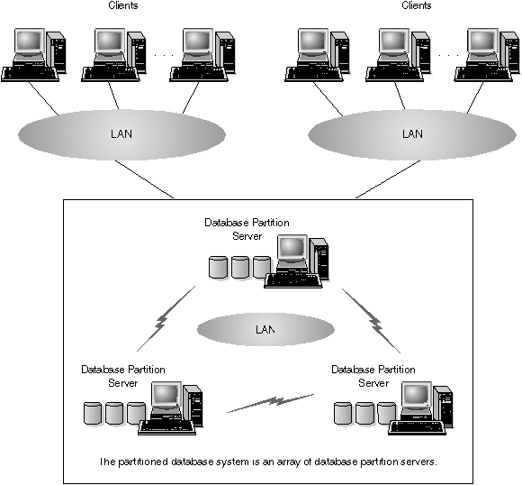

Figure 1 shows an example of a DB2 Enterprise - Extended Edition (DB2 EEE) hardware configuration.
Figure 1. DB2 Enterprise - Extended Edition Hardware Configuration
 |
DB2 EEE can run on a cluster of individual machines interconnected by a LAN. Communications between all database partition serves is handled by a component of DB2 EEE called the Fast Communications Manager (FCM)
The following sections provide information that you should be familiar with before you configure your partitioned database system. Specifically, they describe:
DB2 Enterprise - Extended Edition implements a shared-nothing architecture, therefore each database partition server is the equivalent of a single-partition database system. Thus, the database storage capacity for the partitioned database system is equal to that provided by a single-partition database system multiplied by the number of database partition servers. You can store tables of up to 64 GB (gigabytes) per database partition, where giga is 109. For example, in a database that has 128 partitions, the maximum size of one table is 8 TB (terabytes, where tera is 1012).
You can define named subsets of one or more database partitions in a database. Each subset you define is known as a nodegroup. Each subset that contains more than one database partition is known as a multipartition nodegroup. Multipartition nodegroups can only be defined within database partitions that belong to the same database.
Three default nodegroups are created when you create a database: IBMDEFAULTGROUP, IBMCATGROUP, and IBMTEMPGROUP.
If you want, you can create tables in the default nodegroups IBMDEFAULTGROUP and IBMCATGROUP.
The IBMDEFAULTGROUP nodegroup contains all the database partitions for the database. When you create a database, a database partition is created at each database partition server (node) in the instance.
The IBMCATGROUP nodegroup for the database is created at the database partition server where you enter the create database command. This nodegroup only contains the database partition that is local to the database partition server where the command was entered. This database partition server is referred to as the catalog node of the database because the IBMCATGROUP nodegroup contains the catalog tables for the database.
You cannot directly work with the third default nodegroup, IBMTEMPGROUP. Like the IBMDEFAULTGROUP nodegroup, it also contains all the database partitions of a database. This nodegroup is used to contain all temporary table spaces.
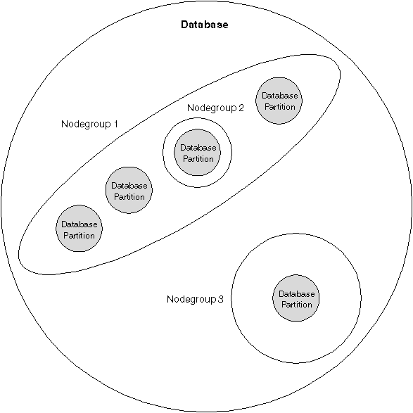
Figure 2 shows an example of a database in which there are three nodegroups. Nodegroup 1 is a multipartition nodegroup made of four database partitions, and nodegroups 2 and 3 are both single-partition nodegroups.
Figure 2. Nodegroups in a Database
 |
When you want to create table spaces for a database, you first create the nodegroup where the table spaces will be stored, then create a table space in the nodegroup. After this, you create the tables in the table space.
You can drop database partitions from a nodegroup, or if you have increased the size of the database system you can add new database partitions to existing nodegroups. For information about adding and dropping nodes in nodegroups, refer to the Administration Guide.
As your database increases in size, you can add database partition servers to the database system for improved performance. This is known as scaling the database system. When you add a database partition server, a database partition is created for each database that already exists in the database system. You then add the new database partition to an existing nodegroup that belongs to that database. Finally, you redistribute data in that nodegroup to utilize the new database partition. For information about scaling databases, refer to the Administration Guide.
Each table defined in a multipartition nodegroup has a partitioning key associated with it. The partitioning key is an ordered set of columns whose values are used in conjunction with a partitioning map to determine the database partition on which a row of a given table resides. The partitioning map is an array of 4 096 database partition numbers.
Columns of any data type (except LONG VARCHAR, LONG VARGRAPHIC, BLOB, or CLOB) can be used as the partitioning key. A table defined in a single-partition nodegroup may or may not have a partitioning key. Tables with only long-field columns can only be defined in single-partition nodegroups, and they cannot have a partitioning key. For more information about creating tables, refer to the SQL Reference.
The use of nodegroups and partitioning keys means that:
For more information about creating nodegroups, refer to the SQL Reference. For more information about using nodegroups, refer to the Administration Guide.
Typically, you configure DB2 Enterprise - Extended Edition to have one database partition server assigned to each machine. There are situations, however, in which it would be advantageous to have several database partition servers running on the same machine. This means that the configuration can contain more nodes than machines. In these cases, the machine is said to be running multiple logical nodes if they participate in the same instance.
With multiple logical node support, you can choose from three types of configurations:
Configurations that use multiple logical nodes are useful when the system runs queries on a machine that has symmetric multiprocessor (SMP) architecture. The ability to configure multiple logical nodes on a machine is also useful if a machine fails. If a machine fails (causing the database partition server or servers on it to fail), you can restart the database partition server (or servers) to run on another machine, using the db2start nodenum command or the Start Node option in the Control Center. This ensures that user data remains available. For more information, refer to the Command Reference or the Control Center's online help.
Another benefit is that multiple logical nodes can exploit SMP hardware configurations. In addition, because database partitions are smaller, you can obtain better performance when performing such tasks as backing up and restoring database partitions and table spaces, and creating indexes.
An instance has its own databases and instance directory. The instance directory contains the database manager configuration file, system database directories, node directories, and the node configuration file. For more information on instances in a partitioned database system, refer to the Administration Guide.
In DB2 Enterprise - Extended Edition, an instance contains all the database partition servers (nodes) that were defined to take part in a given partitioned database system. The instance-owning machine (known as node 0) owns the shared directory where this information is stored. Other database partition servers that are added to an instance are said to be participating in the instance.
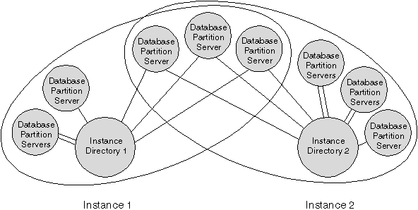
Each instance has different security from other instances on the same machine. This is shown in Figure 3, which shows two separate instances. Instance 1 contains six database partition servers and Instance 2 contains eight database partition servers. (Multiple database partition servers are indicated when more than one line is shown between a database partition server and the instance directory.) The two instances appear to overlap, but this is due to the assignment of two database partition servers to each of the three machines in the middle of the figure.
Database partition servers only belong to one instance. For example, Instance 1 does not contain database partition servers that belong to Instance 2.
 |
You can have multiple instances on the same machine, with each configured differently:
Each instance is owned by the machine where the instance was first created (known as the instance-owning machine, node 0). The instance-owning machine stores information that is common to all of the database partition servers. For information about creating instances, refer to the Administration Guide.
The fast communication manager (FCM) provides communication support for DB2 Enterprise - Extended Edition. Each database partition server has one FCM thread to provide communications between database partition servers to handle agent requests, and to deliver message buffers. The FCM thread is started when you start the instance.
If communications fail between database partition servers or if they
re-establish communications, the FCM thread updates information (that you can
query with the database system monitor) and causes the appropriate action
(such as the rollback of an affected transaction) to be performed. You
can use the database system monitor to help you set the FCM configuration
parameters. For information about FCM-related database system monitor
output, refer to the System Monitor Guide and
Reference.
 | You can specify the number of FCM message buffers with the fcm_num_buffers database manager configuration parameter. For a description of this and other FCM parameters, refer to the Administration Guide. |
You can set up your partitioned database system so that if a machine fails, the database server on the failed machine can run on another machine. MSCS can perform both failure detection and the restarting of resources in a clustered environment, such as failover support for physical disks and IP addresses. On Windows NT, you implement failover support using Microsoft Cluster Service (MSCS). To use MSCS, you require Windows NT Server 4.0, Enterprise Edition, with the MSCS component installed. For more information, refer to the Administration Guide.
On Windows NT, DB2 Enterprise - Extended Edition (DB2 EEE) can take advantage of Virtual Interface (VI) Architecture. VI Architecture was developed through the efforts of various companies to address the needs for a standard high-volume interconnect for data transfer between servers. VI Architecture permits high volumes of data to pass very quickly between clustered servers.
Prior to the release of VI Architecture, communications between database partition servers in a cluster was done through the network infrastructure provided by the operating system. This amounted to processing overhead on the operating system each time any communications between partitioned database servers took place. VI Architecture defines a thin, fast interface that connects software applications directly to the networking hardware, while retaining the robust security protection of the operating system. In a communications-intensive environment, implementing VI Architecture with DB2 EEE can realize significant improvements in overall system throughput of database transactions and queries. For more information, refer to the Administration Guide.